Differential Low-Pass Filter and The Design Formula
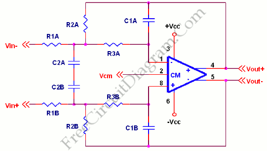
Multiple Feedback (MFB) is the best filter topology to use for differential low pass filters. Here’s the circuit diagram:
To design this filter, a corner frequency is chosen based on harmonic content desired in the waveform. After that, we have to select a value of capacitor. The value of C1 is equal to C and C2 is equal to 2.67 C. The next steps is calculate the starting resistor value “R”. After starting resistor is found, we can find R1 R2 and R3 by this ratio, R1=R2=0.625R and R3=0.36R. If the ratios are presereved, the filter can be scaled up or down in frequency linearly by changing component values. [Source: Texas Instruments Application Note]