RS-485 Data Interface Gives Isolated, Full-Duplex Operation

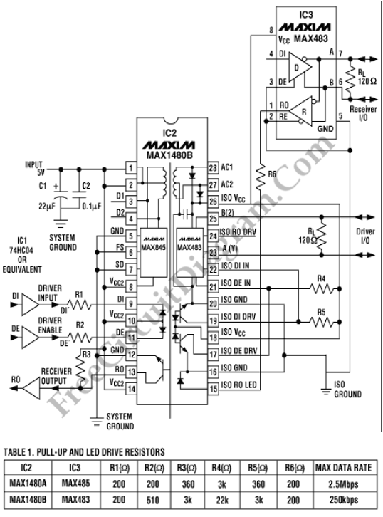
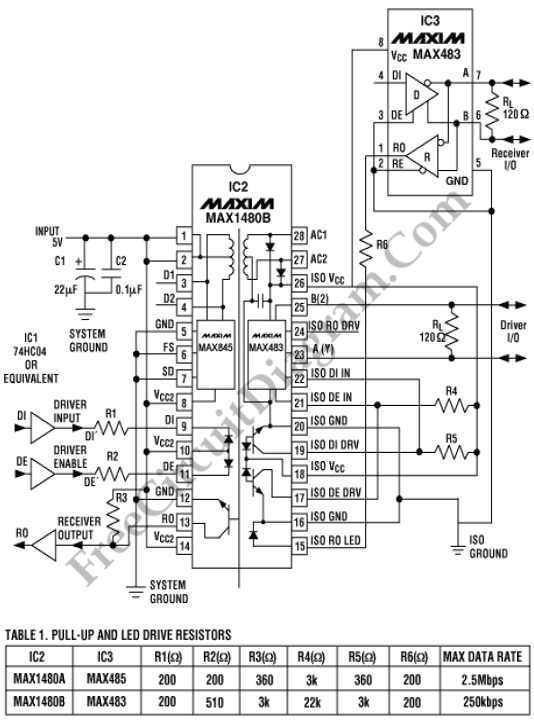
The circuit diagram below is a simple RS-485 circuit. Full-duplex communications (simultaneous transmission and reception) with only two essential packages (IC2 and IC3) is provided by this circuit. For high-noise environments or for long-distance transmission between a computer and it’s peripherals, the simple RS-485 balanced and differential data lines are necessary. Such transmission are difficult, if possible, using the single-ended circuitry of an RS-232 transceiver. Here is the circuit diagram:

Bidirectional, multi-point, party-line communications, with data rates to 10M bits/second (10Mbps) and line lengths to 1200 meters are allowed by RS-485 standard. Noise immunity is provided by differential transmission. Features controlled-slew-rate drivers that minimize EMI and the reflections caused by improperly terminated cables is shown on the circuit below. Enables error-free transmission to 250kbps also available on this circuit. Subtitute a full-slew-rate MAX1480A for IC2, a MAX485 for IC3, and R2-R5 values per Table 1 to achieve data rates to 2.5Mbps.
The half-duplex operation of IC2 to full duplex using IC2’s own dedicated optocouplers is upgraded by IC3 which is powered by the isolated Vcc. To disable IC3’s driver, Pin 3 must be tied low and Pin 4 should be left floating. When active-low DE is low, the driver ouutputs for IC2 and IC3 exhibit high impedance. This will bring active-low DE high enables the output to function as line drivers.
Typically, the isolation barrier in IC2 lasted one minute for 1600Vrms or one second for 2000Vrms. The IC2 digital inputs can be drove through a series resistor by any TTL/CMOS-logic family. The receiver outputs can drive any such logic as well with resistive pull-ups. IC2’s isolated outputs qualified in all RS-485 specifications. [Source: MAXIM Application Note]