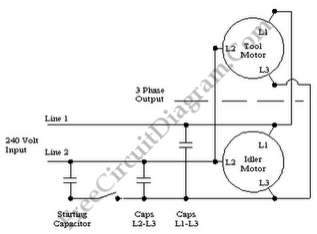
3 Phase to Single Phase Rotary Converter

In the circuit the rotary converter is nothing more than a second motor which is acting as a generator. The tools motor performed this function with the static converter, but at the cost of some loss of power. The idler motor is under no physical load but it cleans up the signal with the rotary converter. The only difference on the figure below is an idler motor is added on the circuit.

Then the static converter, the output of the rotary phase converter is closer to being a true 3 phase source. This will provide more power to the tool motor and also brings it up to speed faster. When you have a motor which is started and stopped frequently, the rotary converter is best served, and you need the full power of the motor. Several different 3 phase tools can be drove by a single rotary converter.
How to setting up the rotary phase converter is the same as the static converter describe above. What we do is only decide the size of the idler motor. The idler motor needs to be larger than the largest tool which will be operated.
Your idler motor should be 125% of your tool(s) motor size since the static converter will provide a motor with 80% of its normal operating power and the rotary phase converter uses a static phase converter as a starter. Your idler should be between 6 and 7 horsepower if your tool is a 5 horsepower motor. I would use a 7 horsepower idler motor since it’s always better to err on the high side. Make sure the current rating of the idler motor is 125% of the sum of the tool motors if the converter will operate more than one tool. [Circuit’s schematic diagram source: 1stcircuits.blogspot.com]