Stereo VU Booster Circuit using Transistors

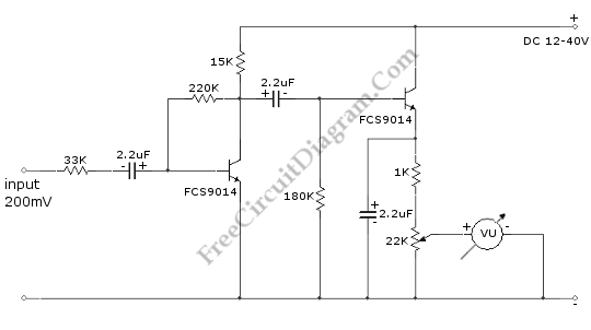
This is a Stereo VU Booster circuit. In this circuit, shown in the schematic diagram, transistor FCS9014 is used. Actually you can use almost any type of small signal NPN transistor. This transistor usually used for regulator and pre-amp circuit. Here is the schematic diagram of the circuit:

The schematic diagram show only one channel, so you have to build one other similar circuit for stereo channel. The input impedance of this circuit is at least 33k. The first transistor is employed to amplify the signal, and the second transistor’s function is for rectifying and buffering. You can see the second transistor’s base is not biased. This means that the positive cycle of the ac signal from 2.2 uF will directly drive the transistor, which is configured as emitter follower. To use this circuit, connect this circuit to audio channel before amplifier module. This circuit can also be connected to the wire connection before equalizer or tone control which will give good output when the equalizer or tone control is used.