AC Line Dropout (Power Failure) Detector

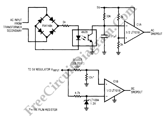
Power dropout detection is often required by digital system driven from the AC line. A memory store command to be issued before DC power falls is allowed by fast AC line drop out detection. The circuit on figure below detects AC dropout by connecting an optoisolator across the power transformer’s rectified secondary. Normally, the LED is turned on by the AC line every 8ms (1/2 cycle of the line), causing the output transistor to reset the 0.01 uF capacitor. The capacitor charges via the 33k resistor when the line drops out. The resultant ramp voltage is compared by C1A to a +5V supply derived reference. The 2k-3k resistors bias C1A to go low (Trace C) with in one cycle of AC line dropout in this case. Typically, before it begins to sag, the DC regulator will supply 50ms-100ms of hold up.
Adequate time is permitted to executed a memory store operation in this hold-up period, which should be verified in any individual application. C1B serves as a final warning that power failure is imminent. When the 5V regulator input drops below the treshold set by the selected resistor shown on the schematic, it goes low. We have to chose this value so that C1B trips when the regulator input approaches its specified dropout voltage. [Linear Technology Application Note]