Positive and Negative Peak Detector Circuit Using CA3130 Op-Amp

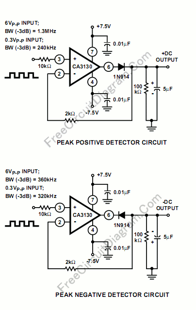
Implementing peak-detector circuits is very easy with the CA3130, as shown in schematic diagram of this circuit. The figure below shows the schematic diagram of the peak detector circuit. The upper section is peak-positive and the lower section is peak-negative circuit.
Please note that with large-signal inputs, the bandwidth of the peak-negative circuit is much less than that of the peak-positive circuit. In this case, the second stage of the CA3130 limits the bandwidth. The time constant of peak-holding-time or peak-decay-time is determined by the 100k resistor and the 5uF capacitor, you can modify their values for different setting of this peak detector circuit. [Circuit’s schematic diagram source: Harris Semiconductor Application Note]