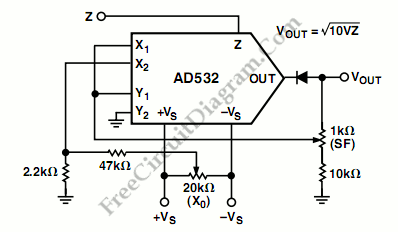
Square Root Mode for AD532 Analog Processor

The following schematic diagram shows us about the connections for square root mode for ADS532 analog processor chip. Similar to the division mode, the multiplier cell is connected in the feedback of the op amp by connecting the output back to both the X and Y inputs. To prevent latch up as Zi approaches 0 Volts, the diode D1 is connected. The Vov adjustment is made with Zin = +0.1 V dc in this case, adjusting Vos to obtain -1.0 V dc in the output, Vout =-√(10 VZ). Gain (S.F) and offset (Xo) adjustments are recommended for optimum performance.

[Circuit’s schematic diagram source: Analog Device Application Note]