Analog PID Controller
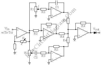
The circuit diagram below shows us about a form of PID controller. The input signal is buffered and amplified by a non-inverting amplifier and the gain of this stage defines the proportional gain P of the controller.The amplified error signal passes in parallel through an integrator (top) a unity-gain amplifier (middle) and a differentiator (bottom) all of which have inverting […]

Read more
Stereo Balance Indicator

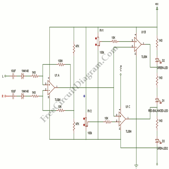
This circuit presents a very simple and useful stereo balance indicator circuit that is based on few common external components. This schematic circuit is very simple to build. An visual indication with LEDs for left , right and center balance is provided by this circuit. Outputs from each channel are fed to the two inputs of IC1 connected as a […]

Read more

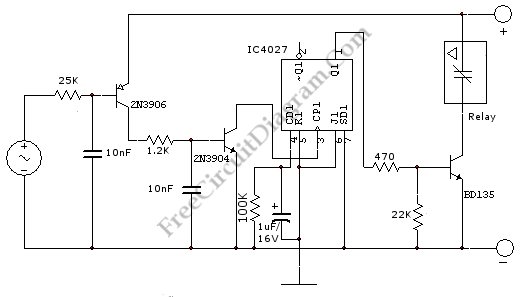
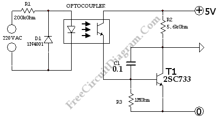
Touch Switch Activated Relay

This is a simple circuit of Touch switch activated relay. This circuit is used to turn on/off electronic relay using touch sensor. This circuit consist of two main parts, they are a decimal counter and an current amplifier circuit. This circuit is need a 5volts power supply. Here is the circuit: As the counter circuit, this circuit uses JK flip […]

Read more

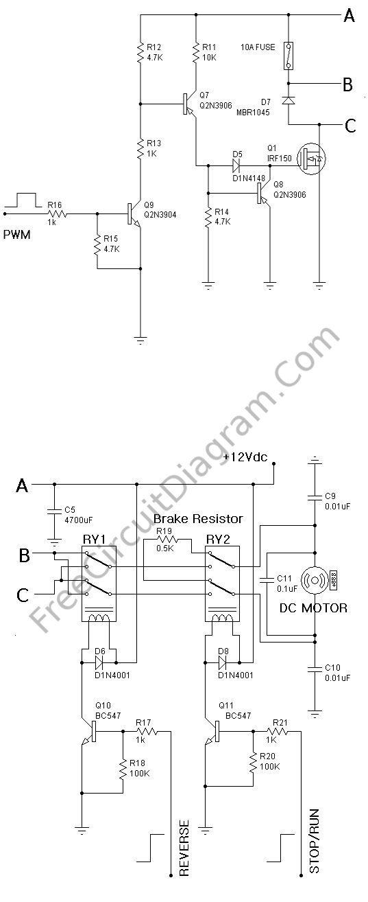
PWM Speed Control with Forward-Reverse and Regenerative Braking

Figure below shows us a PWM Speed DC Motor Rotation circuit. This circuit has two functions, Forward-Reverse and Regenerative Braking function. On this circuit, we can control the speed of DC 12V motor with Power Mosfet IRF150 using a signal PWM. The Relay RY1 work as control Reverse with the digital alarm, change Q10. The Relay RY2 work as function […]

Read more
1 9 10 11 12 13 22