Wheatston Bridge PWM Signal Conditioner
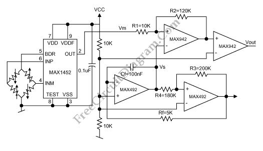
This is a schematic diagram of a Wheatston Bridge PWM Signal Conditioner circuit. This circuit uses the MAX1452 signal conditioner. A ratiometric compensated output for the Wheatstone Bridge is generated by the MAX1452. Then the output of the Wheatston bridge is converted to a PWM output. the PWM-output duty cycle changes accordingly, as the MAX1452 output changes with pressure. the […]

Read more
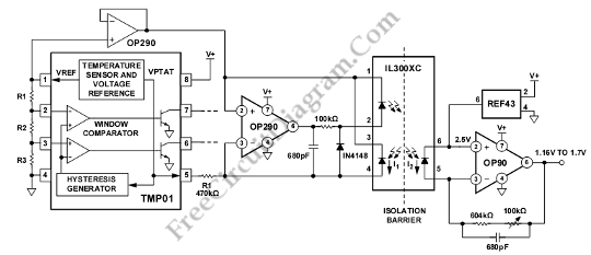
IL300XC Isolation Amplifier for TMP01 Temperature Sensor

This schematic diagram is about IL300XC Isolation Amplifier circuit for TMP01 Temperature Sensor. This circuit is used in an environment that needs to be electrically isolated from the central processing area. This circuit uses an 8-pin optoisolator (IL300XC). IL300XC was chosen because it can operate across a 5,000V. To drive the LED connected between Pin 2 and Pin 1, this […]

Read more

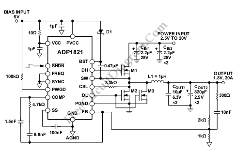
ADP1821 Step Down DC-to-DC Converter

This is a ADP1821 Step Down DC-to-DC Converter circuit. This circuit uses ADP1821 that is synchronous pulse-width-modulated (PWM), step-down controller, inexpensive and versatile. It can drive all N-channel power stage to regulate an output voltage as low as 0.6 V. The output voltages that can be provided by this circuit is from 0.6 V to 85% of the input voltage. […]

Read more

AD596/597 Setpoint Control for Temperature Controller

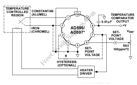
This is a setpoint controller circuit using The AD596/AD597. The thermocouple voltage is amplified, compared to an external setpoint voltage, and cold junction compensated. The device temperature can be monitored if the temperature to be controlled is within the operating range (–55°C to +125°C) of the device. Here is the schematic diagram of the circuit: Setpoint Voltage of AD597 is  […]

Read more

AD586/597 Temperature Transducer (Sensor)

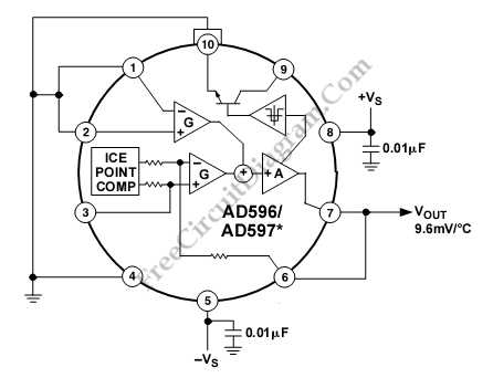
This is a stand alone temperature transducer/sensor circuit. This device uses The AD596/AD597, employing its internal junction compensation temperature sensor inside. This device can be used as temperature sensor by omitting the thermocouple and connecting the inputs (Pins 1 and 2) to common. Here is the schematic diagram of the circuit: The output will reflect the compensation voltage and the […]

Read more

Single Cell 1.5V Hearing Aid

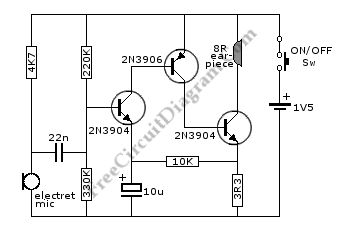
This is a hearing aid circuit with 1.5v supply. This circuit is used to detect very faint sounds, then deliver the sounds to an 8 ohm earpiece. This circuit requires 1.5v input voltage, need only a single cell battery. Here is the schematic diagram of the circuit: This circuit can be assembled in a small board, or you can even […]

Read more

Separate ON-OFF Touch Switch

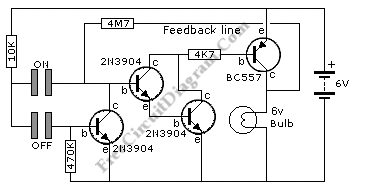
This schematic diagram is about touch switch circuit.  Separate ON and OFF switch improves the ergonomics for safety, since the touching off button when the state is off doesn’t make the system acts in the opposite way: turning ON the system. This accident usually happens when we make wrong assumption of the current state about ON or OFF of the […]

Read more
1 2 3