Posts Tagged ‘Converter’
High-Voltage Generator with HEX FET
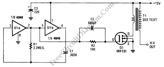
The schematic diagram below show a circuit of high voltage generator. This circuit uses a 4049 hex inverter as an oscillator, and you can use ignition transformer from automotive engine. A fly-back transformer is possibly usable too. The 4049 will drive the IRF731 HEX FET. The Q1 must be heatsinked. Here is the schematic diagram …[Read More]
Three Wire RS232 To RS485 Converter

The schematic diagram below show the circuit diagram of an RS232 to RS485 converter circuit. The EIA-485 standard, a.k.a TIA/EIA-485 or RS-485, is a physical layer standard defining the electrical properties of electronic drivers and receivers using balanced digital signal which is capable of handling multipoint systems. The ANSI Telecommunications Industry Association/Electronic Industries Alliance …

Current to voltage converter circuit can be made using a single resistor, it is very simple since any current will naturally develop a voltage when flow through a resistor. Using an active component, a small developed voltage on a resistor can be accurately measured since we can amplify it to reach a convenient level to …[Read More]
26V-to-5000V DC-DC Converter

This circuit can provide 5,000 VDC from 26 VDC. This circuit has ripple of under 0.01% due to Voltage-doubling capacitors. As sinusoidal oscillator, a 2N217 transistor is used. The diode and the capacitors at the output stage should be of high voltage type. Here is the schematic diagram of the circuit:
Logarithmic Amplifier Using MC1556 Op-Amp

The circuit below is a logarithmic amplifier using an MC1556 op amp. The 10K pot is an offset adjustment. Here is a schematic diagram of one classic example of general purpose logarithmic converter circuit employing LM1556 op-amp: The popularity of logarithmic amplifier is decreasing as the microprocessor and microcontroller chips are getting lower and lower …[Read More]
ADP1821 Step Down DC-to-DC Converter

This is a ADP1821 Step Down DC-to-DC Converter circuit. This circuit uses ADP1821 that is synchronous pulse-width-modulated (PWM), step-down controller, inexpensive and versatile. It can drive all N-channel power stage to regulate an output voltage as low as 0.6 V. The output voltages that can be provided by this circuit is from 0.6 V to …[Read More]
Voltage-to-Pulse Duration Converter

This is a circuit of Voltage-to-Pulse Duration Converter. This circuit is used to convert voltage into pulse duration by combining a timer IC and an OP Amp. This circuit can obtain accuracy up to better than 1%. The output signal is independent of the input voltage and still retain the original frequency. Here is the …[Read More]
| 

