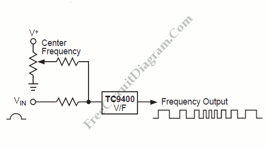
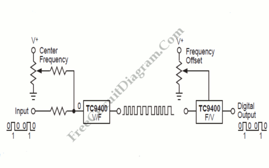
FreeCircuitDiagram Articles Search
Custom Search


PLL FM Demodulator

circuit schematic

A PLL system can be used to implement an FM demodulator. When a PLL is locked on an FM signal, the VCO tracks the instantaneous frequency of that signal. Since the VCO output tracks the FM signal, and the VCO input voltage is proportional to the VCO output frequency, then the VCO input will be [...]


Read the rest of this article [..]

Split-Phase Data Synchronization and Decoding

circuit schematic

A split-phase data signal consists of a series of binary digits that occur at a periodic rate, as shown in waveform A in the timing chart. The weight of each bit, 0 or 1, is random, but the duration of each bit and, therefore, the periodic bit rate, essentially is constant.
A clock that is synchronized [...]


Read the rest of this article [..]

FSK Demodulator

circuit schematic

This FSK demodulator convert the FSK signal to serial digital signal. FSK modulation is used to transmit digital serial data, and we need to demodulate it to get back the digital data at the receiver. Here is the schematic diagram of the circuit:

This demodulator circuit uses 2225/2025  Hz for  mark/space coding, and this frequency is [...]


Read the rest of this article [..]

Radio Modem Circuit

circuit schematic

This radio modem is popular for amateur radio packet application. This radio modem is powered by the data and control lines, so it need no additional power supply. Just plug to your standard RS232 port and this modem will work. As seen in our previous modem circuit, this radio modem circuit also uses TCM3105 modem [...]


Read the rest of this article [..]

BELL 103 Compatible FSK Modem Circuit

circuit schematic

This circuit uses MM74HC942, a single chip low-speed modem which is compatible with Bell 103 standard. This Bell 103 modem circuit is run at 300 baud in full duplex (bidirectional). The frequency and sine wave synthesizer inside this modem chip generate phase-coherent FSK modulation for the best bit accuracy. Here is the schematic diagram of [...]


Read the rest of this article [..]

Power Line Modem Circuit for Home Automation Application

circuit schematic

Imagine you have a master controller device that control other devices in your house, and you don’t need to install any additional wires to facilitate the data communication between the master controller and the controlled devices. Yes you’s life will be easier since all you need is just plugging your devices into your power line [...]


Read the rest of this article [..]


 Page 1 of 2  1  2 »