Posts Tagged ‘Signal Processing’
Tremolo Effect Circuit for Electric Guitar or Other Musical Instruments

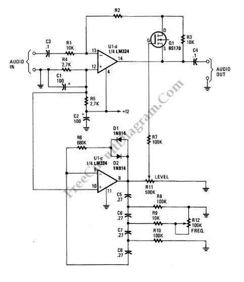
Tremolo circuit is a kind of sound effect. We can see this type of effect is applied in guitar effect pedals. Tremolo effect is produced if we modulate the amplitude of an audio signal. The shape of modulating signal can vary from square wave, sawtooth, or sine. When we use a square wave, then the …[Read More]
Binaural Synthesizer/Mono to Stereo Converter for Small Speaker/Phones

This simple circuit can be used to drive two high-impedance loudspeakers or stereo phones, taking monophonic input (one channel), to produce a stereo signal which spread along the midway between loudspeakers when the input signal contain many frequency components. This circuit has two channels, left and right, right channel has high-pass active filter and left …[Read More]

Missing pulse detector will receive a source of repetitive pulse in normal condition. The output of this detector circuit will be inactive for normal condition (output pin 3 of 555 IC will be high, turning off the LED indication). If now the input pulse is missing, delayed, or stopped, then the output of this detector …[Read More]
60-dB Range Compressor For Audio

A compressor circuit shown in the schematic diagram below can produce consistent output of 1.4V P-P over entire 60dB range that is very useful for audio level/volume stabilization. As the main components, this circuit uses a 741 opamp and JFET. With input range of 20mV to 2oV, this circuit has delay time of 0.4s (decay …[Read More]
Analog Multiplier-Divider with 4136 Op-Amps

This unique circuit below can be used as divider and multiplier. This circuit is formed by all four sections of a 4136 . The Q1 through Q4 can be any PNP transistor, but that must matched transistors. The transistor matching determine the acurracy of the divider and multiplier circuit. Here is the schematic diagram of …[Read More]
Difference Of Squares Analog Computing

Because the differential input capability of the AD532, algebraic solution of several interesting functions such as difference of squares, (X2-Y2)/10V is allowed. The following figure shows us about the configuration of AD532 in the square mode, with a simple unity gain inverter connected between one of the signal inputs (Y) and one of the inverting …[Read More]
Square Root Mode for AD532 Analog Processor

The following schematic diagram shows us about the connections for square root mode for ADS532 analog processor chip. Similar to the division mode, the multiplier cell is connected in the feedback of the op amp by connecting the output back to both the X and Y inputs. To prevent latch up as Zi approaches 0 …[Read More]
| 

