Posts Tagged ‘Switched Power Supply’
TLC497CN Negative Supply Generator
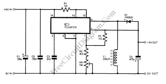
Negative supply from positive supply is needed if the circuit need both positive and negative supply while we have only positive supply. The circuit shown in the schematic diagram below is a negative supply generator, built using a TLC497CN integrated circuit. The TLC497CN is used as the main switching circuit, and it can provide negative …[Read More]
Variable Frequency Switch Mode Regulator

This voltage regulator circuit operates in switch mode. Using the configuration shown in the schematic diagram, this circuit has variable switching frequency, depends on the input voltage and load condition. The core controller of this switching regulator is a TL497 switching regulator controller IC. Here is the schematic diagram of the circuit: When the load …[Read More]

The circuits. To produce any output voltage, an external feedback resistors can be added. The sLM2576 is a Switching Regulator that can produce 15, 12, 5, 0r 3.3V output voltage from maximum supply voltage of 60V or 40V. This LM2476 featured with voltage reference, switch and feedback path for use in either the negative …
High Side Current Sensing for High Side Switching

Sometimes, there are unexpected solenoid and excessive corrosion occurs on current sense circuit. Corrosive effects can be occurred because of the differential voltage between the ground and the load. To reduce that possibility, the shunt and the switch are placed on the high side. When switch is off, the battery is removed from the load, …[Read More]
High Side Current Sensing for Low Side Switching

An AD8205 can be used to make a high-side current sense with a low side switch. Besides AD8205, an inductive load (solenoid) and a resistive shunt are added in this circuit. The resistive shunt is placed on high-side and the switch is placed on low-side, so that all current measurements, including the the re-circulation current, …[Read More]
ADP1821 Step Down DC-to-DC Converter

This is a ADP1821 Step Down DC-to-DC Converter circuit. This circuit uses ADP1821 that is synchronous pulse-width-modulated (PWM), step-down controller, inexpensive and versatile. It can drive all N-channel power stage to regulate an output voltage as low as 0.6 V. The output voltages that can be provided by this circuit is from 0.6 V to …[Read More]
TPS108x Versatile Boost Converter

This is Versatile Boost Converter circuit using TPS108x. The TPS1081 has chosen because it is suitable for application that requires up to 20 V and 100 mA to drive each column of a passive-matrix OLED (PMOLED). the TPS61080 is suitable for application that requires less than 10 V and only tens of milliamps per column …[Read More]
| 

