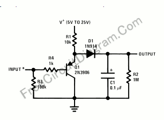
Single Transistor Half-Wave Peak Detector Circuit

Using only a single transistor and few passive components, you can build a fairly sensitive peak detector. circuit This peak detector circuit is suitable for audio application, since the average sum of positive and negative cycle of audio signal has equal value. You can find a peak signal although you only detect the peak of positive cycle. Here is the circuit’s schematic diagram:
The core of this peak detector circuit is a voltage follower, but uses pnp transistor rather an npn one. The voltage at Q1 emitter will follow the voltage at its base (approximately same with the input voltage), but added with base-emitter voltage of Q1. When the input voltage is zero, the emitter will be 0+Vbe, or about 0.6V. This Vbe drift is useful beause we employ a silicon diode with the characteristic of forwad voltage bias is equal to this voltage drift. This 0.6 voltage drift make the diode ready to conduct although the input signal is exacly at zero. Although this peak detector circuit implement diode forward bias compensation, the circuit is still not accurate enough for the input level below 100mV, you need a more precise peak detector circuit if you concern with such low level signal. [Circuit’s schematic diagram source: National Semiconductor Application Notes]