Closed Loop PWM Motor Control

Closed Loop Motor Control
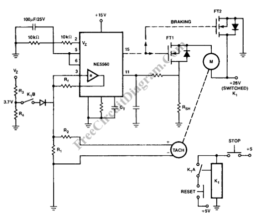
Closed loop (servo) control is used to make a constant speed motor control. Constant speed means that the speed of the motor will be kept constant although the load is change, or even when the electric supply voltage is also changed. The circuit maintain the speed at a constant value by sensing the actual speed using a tachometer. If the speed is slowing down because of the load become harder, or because the electric supply get slightly lower, the circuit will automatically increase the power transfer to the motor by increasing the duty cycle of the motor drive, until the sensed speed by the tachometer and the reference speed has no difference.

Motor Control Circuit
The circuit is unipolar, means that you cannot change the motor direction by the control signal. This switched mode motor drive (SMMD) uses NE5560 as the core of the circuit, suitable for small DC motor. The power switching component is a single Philips BUK456-100A Power MOSFET. It has current handling capability over 30 A, and 100 V voltage rating of VDS, and 0.057 Ohms RDS-ON. The nominal frequency of the PWM is 10 KHz, but much higher frequency is possible. It is also a good idea to operate the switching over 20 KHz to avoid audible interference to audio equipments. VGS, the peak gate to source voltage, is 15V to ensure minimum RDS(ON), so the power loss in the PowerMOS switch is minimum.
Torque Limiter
This circuit include a current sense resistor, placed in the source lead to monitor motor drive current on a cycle-by-cycle basis.This resistor value is set to produce the error amplifier threshold voltage at the desired maximum current. When this threshold voltage is exceeded, the NE5560 then automatically limits the duty cycle of the PWM output. You can say this is a torque limitter feature, which is actually an unavoidable effect of the switching device protection by limiting the current.
Motor Start-Up and Dynamic Braking
At power on, to avoid power surge, a slow start network (Pins 2,5,6) gradually ramps up the duty cycle. Forcing the input of the error amplifier By K1B produce a fixed duty cycle control for braking. The over-current circuit still work during braking. [Circuit schematic diagram source: Power Semiconductor Applications from Philips Semiconductors]