Humidity Sensor

Introduction
Interfacing humidity sensor can be difficult because of the sensor’s drive requirement and their wide dynamic range. We can customize the circuit to obtain reasonable accuracy within the chosen range by carefully selecting the devices that comprise the analog front end. Here we present a case study to design analog signal conditioner for Phys-Chem Scientific Corp.1 model EMD-200o humidity sensor.
Design Requirements
The Phys-Chem sensor is an accurate resistance-type relative humidity (RH) sensor that is small and low cost. The system utilizing this sensor would be easily maintainable, since we can replace the sensor without recalibration, as the sensor has a well-defined stable response curve. The high performance of this sensor requires a high precision analog front end with only few calibration tweaks, but must be low cost and works with 5 volts supply. A sine or square wave with no DC component is required for the excitation of this sensor. Also, this sensor has very wide range of dynamic reactance (700 Ohm to 20MOhm). This wide dynamic range (about 90 dB) introduces design challenge to obtain full RH range performance.

The Circuit Design
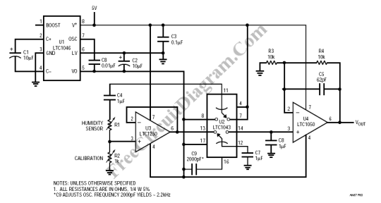
The feature of zero drift of operational amplifiers LTC1250 and LTC1050 is used for this circuit. This circuit uses also a precision instrumentation switched capacitor block LTC1043. A microvolts levels of DC accuracy will be maintained by this circuit, so we don’t need a true RMS-to-DC or log converter that will cost more and will be unstable as the temperature changes. This circuit use only a single 5 volt supply, since we provide LTC1046 that convert the 5V supply into -5V supply. This negative supply is used by U2, U3, and U4.
The excitation for the sensor is provided by U2A, part of LTC1043 switched capacitor building block. This excitation is an AC square wave that swing between 5+ and -5 volts with approximately 2.4 kHz, which is one-half of the auto zero rate of U3. The deviation from the Phys Chem response curve taken at 5 KHz is believed to be insignificant. The full-scale setting is provided by variable resistor R2. Because the resistance of the sensor is 700 Ohm at approximately 90% RH, setting the R2 at 700 Ohm will result in 2:1 voltage divider. This voltage divider will result in overall gain of one if combined with the U4 gain (gain=2). To function properly, U3 must be included, otherwise, C4 and C7 will form a voltage divider that depends on the RH sensor resistance. U3 is a precision auto zero operational amplifier with auto zero frequency about 4.75 kHz. The “lower” switch U2B samples the U3 output and provides this sample to the U4 input. U4 is set to provide a gain of 2.
Digitizing the output of U4 is easy. The range of humidity that can be sensed depends on the resolution of the converter. The full-scale output (approximately 90% humidity) is essentially independent of the number of bits in the ADC, but the dry (low RH) end of the scale is dependent on the A/D resolution. As an example, a 12-bit DAC will process humidity signals that translate to approximately 20% RH, since the voltage output at this humidity is approximately 2.3mV, while 0.5LSB is 1.2mV. To read lower RH down to 10%, converting 350uV signals would require a 16-bit converter. A 16 bit ADC is expensive, so it is much more economical to use a 2-channel 12-bit converter that changes ranges somewhere in the humidity range. [Circuit’s schematic diagram source: Linear Technology Application Notes]