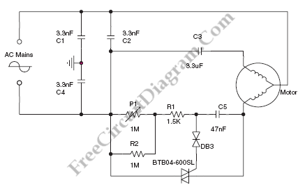
Synchronized TRIAC for Small Induction Motor Speed Control

We can use this circuit diagram to adjust the speed of a low-power induction motor, such as those which can be found in fan application. The function of capacitors C1, C2 and C4 is to filter the noise coming from TRIAC commutations. X2 technology is used for C2 capacitor whereas Y2 technology is used for C1 and C4 capacitors. Here’s the circuit diagram:

[Source: STMicroelectronics Application Note]