Three Op-Amps Instrumentation Amplifier

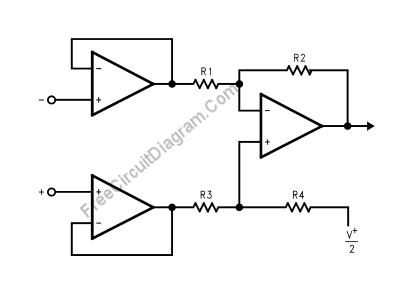
Using LMV721/722 or any other high impedance op-amps, you can build an instrumentation amplifier using standard three op-amps instrumentation amplifier circuit. The figure below shows the circuit’s schematic diagram.
The final stage of this instrumentation amplifier is a differential-input, differential-output amplifier, with two voltage followers feed its inputs. These two voltage followers assure that the input impedance is over 100M. R3 should equal R1 and R4 equal R2. The gain of this instrumentation amplifier is set by the ratio of R2/R1. For good CMRR over temperature, low drift resistors should be used. Matching of R3 to R1 and R4 to R2 affects the CMRR. Making R4 slightly smaller than R2 and adding a trim pot equal to twice the difference between R2 and R4 will allow the CMRR adjustment. [Circuit’s schematic diagram source: National Semiconductor’s Application Notes]