LM1893 Powerline Audio Transmission

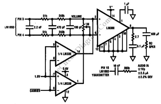
This is Powerline Audio Transmission circuit using LM1893. This circuit uses LM1893 that is designed to allow analog data reception and transmission. The carrier is modulated by base-band audio-bandwidth signals FM passing through the tuned transformer onto the power line. The receiver PLL will demodulates the modulated carrier linearly. Here is the schematic diagram of the circuit:

External audio amplification and filtering is needed because the receiver data path beyond the phase detector will pass only digital signal. To build the carrier detect and mute, this circuit uses a single LM339 quad comparator. To minimize noise, especially line-related correlated noise, the filter bandwidth is held to minimum. The connection to LM1893 is only shown as connection to its pins, refer to LM1893 datasheet for more information on how to interface the integrated chip to the powerline. [Circuit’s schematic diagram source: National Semiconductor Datasheet]