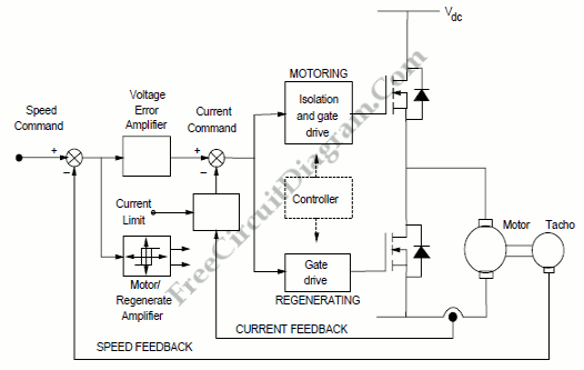
DC Motor Control System Block Diagram

A schematic arrangement for a two quadrant controller is shown on figure below. This figure show us the outer speed control loop and the inner current control loop. The tachogenerator derive the speed feedback signal, although alternatively an approximation to the motor speed can be derived by feeding back a signal proportional to the motor voltage, (AVF). For servo applications, position feedback can be included by using a position encoder on the motor shaft. The tacho- output voltage is compared with a speed reference signal by the feed feedback loop. The current reference command is given by the voltage error signal.

In the inner control loop, the current command signal is compared with the actual motor current. A current limit setting which protects the motor and the devices from overcurrents is included in this control loop. The current demand is maintained below the maximum level by this current limit setting if the controller demands a large speed change. Motoring or regenerating operation is detected directly from the polarity of the voltage error signal. This will be used to determine whether it is the top or bottom MOSFET which is controlling the current. To ensure that control does not oscillate between the motoring and regenerating modest low motor currents, the motoring/regenerating logic circuit includes some hysteresis.
By controlling the switching sequences to the main PowerMOS devices, there are several possible ways of controlling motor current. The motor current is compared with the reference signal and allowed current ripple tolerance in tolerance band control. If the actual current is greater than the allowed maximum value of the tolerance band during motoring operation, then the output comparator turns off the gate drive to the power MOSFET thus allowing the motor current to fall. Then, when the comparator turns the MOSFET back on, the current freewheels until it reaches the lower limit of the tolerance band. The effective switching frequency is variable if we using this current control strategy. It’s all depending on the rate at which the armature current changes, but the peak to peak current ripple in the system is constant. Alternatively, using a PWM method current control, the devices can be switched a constant frequency. The current error signal is compared with a fixed frequency triangular wave. Then the output of the comparator is used to provide the signal for the main switching devices. The power device is switched on when the error signal is greater than the triangular wave and the device is switched off when the error signal is less than the triangular carrier. [Block diagram source: nxp.com]