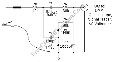
Automatic AF-RF Probe

Using this automatic probe, you can see measure both audio signal (AF) and radio signal (RF). If audio signal is being measured, the path of the signal is via C1. Audio signal can’t pass the C2 since the capacitance is very small and having very high impedance for audio frequency signal.
If you measure high frequency (radio frequency, RF), now C2 has low enough impedance to pass the signal to the rectifier D1 and D2. Not only rectifying the signal, D1 and D2 also double the DC level at C3. You can see the envelope or strength of RF signal with oscilloscope or voltmeter. [Circuit’s schematic diagram source: lh-electric.4t.com]