Voltage Controlled Oscillator with Varactor

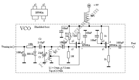
This is a Voltage Controlled Oscillator (VCO) circuit. This circuit is based on Hartley oscillator. The frequency depend on the value of C1 and L1. The oscillation-frequency will change as the change of the capacitance in the varactor BB132 by The Vtuning voltage. The maximum frequency that can be changed is determined by th value of C2. For large frequency change, the value of c2 must be large as well. Here is the schematic diagram of the circuit:

This circuit uses two dual-gate FET. First FET is a Hartley oscillator which the value of C1, L1, C2 and the varicap diod determine the frequency. The span of this VCO is set by C2. Second FET is an amplifier. This circuit has gain of less than 1, however the oscillator will not be loaded and the current will be higher. The turn of L1 and the frequency determine the output amplitude changes. The amplitude can be set by changing the voltage on g2 at FET1 and if lower amplitude is needed, just add the resistor to ground. This circuit has highest gain because g2 is connected to Vcc through R1. [Circuit’s schematic diagram source: VCO]