Active Antenna With Gain (Booster)

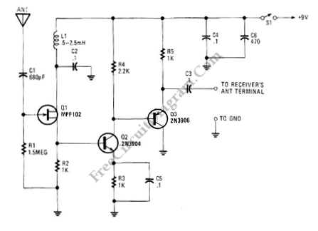
This is an active antenna circuit with gain. This circuit is used to bost the signal. This circuit is made from a few transistors and other components. This circuit can provide RF gain of about12 to 18 dB. This circuit uses Q2 as a voltage amplifier. the RF signal direct-coupled from Q1’s Source terminal to the base of Q2. The Q3 is configured as an emitter-fallower amplifier which match and isolate the gam stage from the receiver’s RF-inputcircuitry. Here is the schematic diagram of the circuit:
The bias of Q2 is set to 2V by the value of R2. The value of R2 can be increased to 1.5KΩ if the voltage is less than 2V. The power source noise never reach the FET because of inductor L1. Set value of C1 to 0.002 μF if need to go to below 100 kHz. The antenna is Short pull-up type.