Two Transistors Wireless Microphone (FM Transmitter)

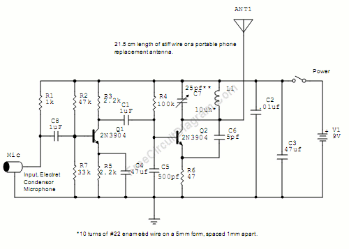
Please be warned if operating this circuit might violate the regulation of your country, because this FM transmitter circuit radiate strong radio frequency to the environment. This wireless microphone is very sensitive, pick up every sound in the 20m radius, and transmit the radio signal up to 2 kilometers in open air. Here is the schematic diagram of the circuit:
The first transistor (Q1) is the pre-amplifier for the microphone, and you can ommit this circuit if you don’t want to transmit the sound picked up by the mic, for example you can can connect your mp3 player directly to C1. The core of this FM transmitter circuit is Q2, a modified Collpits oscillator that the frequency is determined by L1, C4, C6, and the transistor’s internal base-emitter capacitance. The antenna use 1/16 wave length to compromize between the efficiency and the size. If you want the microphone to be less sensitive, you can replace the R1 by a higher resistor, try 10k or 22k, and this might overcome the feedback problem if you use this wireless microphone FM transmitter for a public address system.