Single Chip Thermocouple 4-20mA Current Loop Transmiter Circuit

Thermocouples give many benefits compared to thermistor/RTD (Resistance Temperature Devices). Some advantages of thermocouple are their wider temperature range, their reliability, and their consistency over long period of time. In some cases, thermocouple calibration is even unnecessary. Thermocouple temperature sensors are widely used in temperature controllers for boilers, oven, pressurized reactor, even in high temperature furnace. A general purpose temperature data logger usually provide many transducer interface, and providing interface for many types of thermocouples is a must, beside other sensor like thermistors.
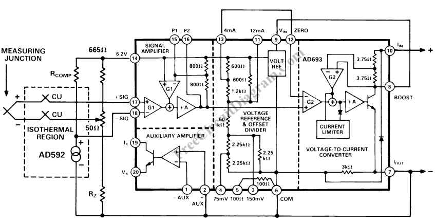
For industrial application, 4-20mA current loop interface is common to transmit the temperature sensing from the thermocouple probe. A signal conditioner and current loop transmitter can be build with only a single chip AD693 integrated circuit. Here is the thermocouple transmitter circuit diagram.
At first, you might see the circuit is very complicated, but you’ll find that most of the complicated circuit reside inside the chip, so actually you need only four resistors and a low cost temperature sensor AD592 or AD590 for cold junction compensation to make a complete high performance thermocouple ransmitter with AD693.

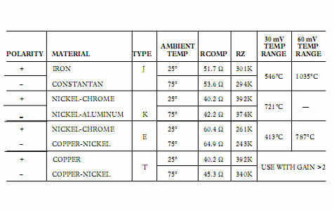
This circuit design enable us to choose many type of thermocouple types. K type thermocouple, type T thermocouple, as well as J and E type can be easily used in the circuit. From Table, simply choose the type of thermocouple and the appropriate average reference junction temperature to select values for RCOMP and RZ. The CJC voltage is developed across RCOMP as a result of the AD592 1 uA/K output and is added to the thermocouple loop voltage. Zero adjustment correction is provided by the 50 ohm potentiometer, and this circuit also translates the Kelvin scale of the AD592 to °Celsius. Calibrating the circuit is easy, just put the thermocouple in an ice bath (or use a thermocouple simulator set to 0) and adjust the potentiometer for a 4 mA loop current.
The span of the circuit in °C is determined by matching the signal amplifier input voltage range to its temperature equivalent via a set of thermocouple tables referenced to °C. For example, the output of a properly referenced type J thermocouple is 60 mV when the hot junction is at 1035°C. The Table lists the maximum measurement temperature for several thermocouple types using the preadjusted 30 mV and 60 mV input ranges.
More convenient temperature ranges can be selected by determining the full-scale input voltages via standard thermocouple tables and adjusting the AD693 span. For example, suppose only a 300°C span is to be measured with a type K thermocouple. From a standard table, the thermocouple output is 12.207 mV; since 60 mV at the signal amplifier corresponds to a 16 mA span at the output a gain of 5, or more precisely 60mV/12.207 mV = 4.915 will be needed. Using a 12.207 mV span in the gain resistor formula given in “Adjusting Input Span” yields a value of about 270 ohm as the minimum from P1 to 6.2 V. Adding a 50 ohm potentiometer will allow ample adjustment range. With the connection illustrated, the AD693 will give a full-scale indication with an open thermocouple. [Circuit’s schematic diagram source: Analog Devices Application Notes]
