Field Strength Meter

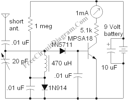
This instrument is very useful for radio frequency (rf) engineer and hobbyist, especially when he/she has to adjust the final rf transmission. Setting up an antenna impedance matcher is one of the example. Here is the schematic diagram of this rf meter circuit:

The circuit use only one transistor (MPSA18) as the active component. The signal strength meter display uses analog meter (1 mA full scale) . This rf field strength meter has no absolute scale if we don’t calibrate the scale using a standard instrument, but the important thing for this uncalibrated rf meter is that it can display the changes of an rf field when we calibrate the antenna or the matching network for the rf transmitter-antenna loading. If we are tuning the antenna size or the transmitter-antenna matcher filter, then just observe the analog meter to get the maximum deflection.
Look at the transistor circuit, the base of the transistor is biased by the voltage from 1 mega ohm resistor, and connected to 1N914 diode to ground. The voltage at this resistor-diode connection is around 0.6-0.7V, and delivered to the base of the transistor via the RFC (Radio Frequency Choke) inductor. This voltage bias is needed to make the transistor ready to conduct. Using such bias, the signal received from the antena doesn’t have to reach 0.6V base-emitter barrier to make the transistor works. The bias voltage is set by the diode just below the point at where the transistor begin conducting, it means that the circuit won’t draw any current from battery if there’s no received rf signal, so it doesn’t need a power switch to cut the power consumption of the supply (the battery), just make sure to move it away from strong active rf transmitter when this device is not in use. [Circuit schematic diagram source: techlib.com]