PWM Motor Control With Forward, Reverse, and Break Operation

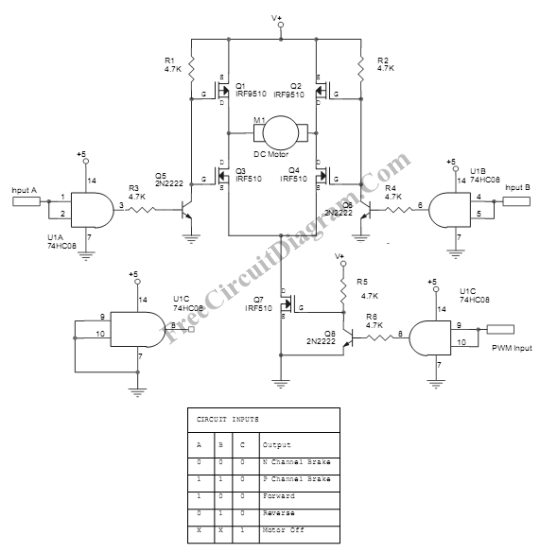
This PWM motor control circuit provides many controls for DC motor. You can control the DC motor to rotate forward, reverse, or break until it stops. Here is the schematic diagram of the circuit:

The circuit uses MOSFETS bridge to drive the motor, controlled by some logic gates and small bipolar transistors. The motor voltage can be 10-20 Volts and the current should be 8 Amperes at maximum. The MOSFET should be installed with a proper heat sink. The V+ input should be supplied with the DC motor’s operating voltage (10-20 Volts). Although the MOSFET is designed for 100 Volt operation, you can only use maximum voltage of 20 Volt because the voltage is also used for driving the gate, that is normally limited to 20 Volts. The minimum value for this supply voltage is 10 Volts since the gate won’t be fully opened if the voltage falls below 10 Volts. You can choose many types of DC motors that operates on 10-20 Volts for this application.