Colpitts Crystal Oscillator

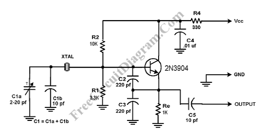
Crystal Colpitts oscillator can be implemented using a transistor and a parallel mode crystal. Here is the schematic diagram of the circuit:

In this circuit, the crystal acts as an inductance. A large value capacitive divider is used between gate, source, and ground, and a small series capacitor is placed in the crystal circuit. You should choose the components values so that C2+C3 to C1 ratio has the highest possible value. The ratio of 5 to 10 to 1 is usually used. The schematic shows the typical values. This circuit introduce a little loading on the crystal. The relatively high values of C2 and C3 “swamp out” variations and drift caused by variations in device characteristics. Frequency can be fine tuned with C1. A clean enough sine wave appears at the emitter of the transistor.