OP90 4 mA to 20 mA Current Loop Transmitter

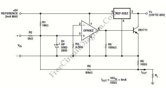
An output of 4 mA to 20 mA that is linearly proportional to the input voltage is provided by the current transmitter on figure below. Line rejection is 0.0005%/volt and linearity of the transmitter exceeds 0.004%. Here is the schematic diagram of this current loop circuit:
The REF-02EZ provides biasing for the current transmitter. The output current is regulated by OP90EZ to satisfy the current summation at the noninverting node:
Iout = 1/R6((Vin.R5)/R2 + (5V.R5)/R1)
Iout = (16/100 ohm)Vin + 4mA
That’s will give a full-scale output of 20 mA with a 100mV input. By adjusting R2, we can provide a offset trim and adjustment of R1 will provide a gain trim. Since the noninverting input of the OP90 is at virtual ground, these trims do not interact. The input voltage spike will be prevented by D1 (the Schottky diode) from pulling the noninverting input more than 300 mV below the inverting input. Without diode, such spikes could cause phase reversal of the OP90 and possible latch-up of the transmitter. This circuit has compliance from 10V to 40V. For transducer excitation, the voltage reference output can provide up to 2 mA. [Circuit’s schematic diagram source: Analog Application Note]