Discrete (Transistors) Schmitt Trigger

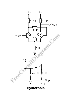
Another circuit (from Horowitz and Hill) is shown below. The circuit is almost the same except that the base of Q2 is not connected to the ground. The voltage at the emitters, Ve, is the important thing here. Q1 is off and the output goes low when the base of Q1 rises to 0.7V above Ve if the input is at low voltage. Due to the extra current from Q1, Ve rises as this point is approached. Ve decreases when Q2 saturates, so the input voltage must be lowered further to turn off Q1 and re-establish the original state. Build the circuit and test it, measuring VE as a function of Vin, going from low to high and back to low again, noting the transition voltages.

It will be easier to do this with the X-Y display of the oscilloscope. To sweep the input voltage and display this on CH 1, use a function generator while the output of the circuit is shown by CH. It is easy to determine the trigger voltages in this way. You can see the graph below. The arrow show the direction of variation. The word “hysteresis” comes from the Greek for womb, and the enclosed area is the reason for the choice of the term. This circuit can be called has memory because the state of the circuit depends on the past history. Find other circuit diagrams collection and their explanation at http://mysite.du.edu/~etuttle/electron/elecindx.htm.