LM1893 Powerline Audio Transmission
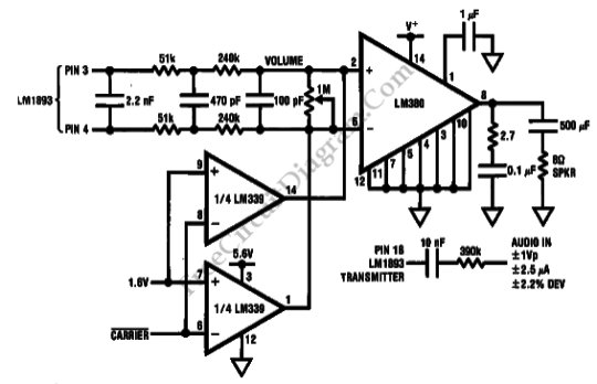
This is Powerline Audio Transmission circuit using LM1893. This circuit uses LM1893 that is designed to allow analog data reception and transmission. The carrier is modulated by base-band audio-bandwidth signals FM passing through the tuned transformer onto the power line. The receiver PLL will demodulates the modulated carrier linearly. Here is the schematic diagram of the circuit: External audio amplification […]

Read more
Discrete Bass Booster Circuit

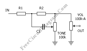
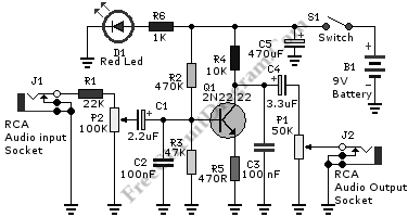
This bass booster circuit can be used filter the input signal as part of internal circuit of an active subwoofer circuit. This circuit is not only boost the bass (low) frequency, but also attenuate high frequency as well. You might consider this circuit as low pass filter, since the high frequency response is not flat, not really as expected in […]

Read more

Digitally Controlled Phase Shifter

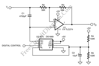
As shown in a schematic diagram below, this circuit implementation of phase shifter circuit  is well suited to using digital potentiometer  to control the resistive control element of  the phase shifter. The phase at a given frequency is now under control of a digital signal using this circuit which is optimized for phase-shifting over the audio range. By using a […]

Read more

Bandpass Filter’s Gyrator Frequency Calculator

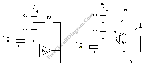
Gyrators are synthetic inductors, which are often used to form bandpass filters. As shown in the two examples here, the active buffering device can be a transistor or op-amp. This type of bandpass filter is commonly used in graphic equalizers and other frequency control circuits such as tone controls. In the gyrator frequency calculator here, enter the values of R1, […]

Read more

Eliminating LED Pop/Click Noise

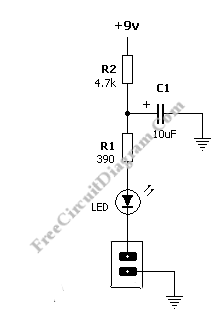
Typical LED indicator consist of resistor (R2) and LED, connected in series with a switch.  When the switch is closing or opening, a glitch noise may occur at the supply line. To avoid this noise, R2 and C1 are added to the indicator circuit and value of R1 is adjusted. Very slightly delay is provided by the R2-C1 circuit which […]

Read more

Passive Baxandall Tone Control (2 Band Equalizer)

Variation of the famous Baxandall circuit is shown in the passive circuit in figure 1. Smoothly increasing +- 6 dB/octave slope of boost or cut is the feature of this circuit. Although the “shelves” are outside the audible range with these component values, the bass and treble filters have a shelving response. The threshold and shelving frequencies is predicted by […]

Read more
1 7 8 9 10 11 21