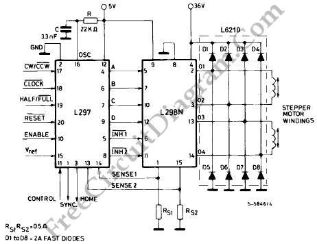
Digital Encoder Circuit Using Stepper Motor
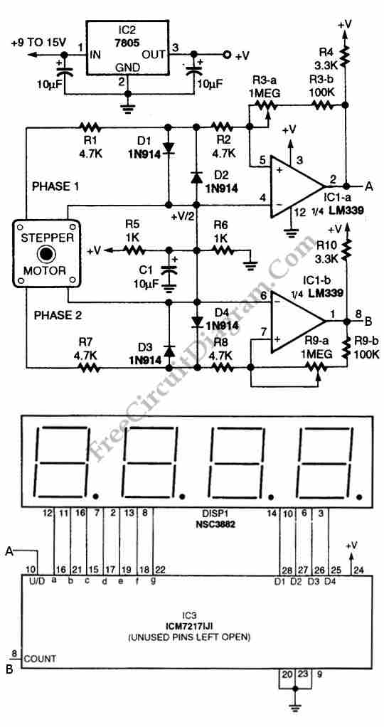
Using circuit depicted in the schematic diagram below, the direction and shaft rotation of stepper motor can be seen on the LED display. Alternative to digital rotation encoder as a digital encoder input, this circuit uses a stepper motor. Here is the schematic diagram of the circuit:
Read more