Frequency To Voltage Converter: Change Your Voltmeter To Frequency Meter

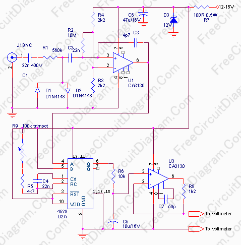
Frequency meter can be used in speed sensor, tachometer, or any measurement of repetitive signals. This frequency to voltage converter (FVC) can be used to turn your analog or digital voltmeter into a tachometer. The circuit’s schematic diagram is shown below.
The circuit consist of three blocks. The first block is a squarer, change the input signal to a square wave. This block is protected from high voltage input up to 400V , but remember this works only if the capacitor C1 is rated for 400V. This input impedance is approximately 560k, so it’s safe to connect your ignition pick-up coil in parallel with your CDI (capacitor discharge ignition) circuit without any problem. The supply is protected from voltage spike by Zener diode D3.
The second block is a retriggerable monostable multi vibrator. This monostable multi vibrator convert the pulses to give fixed width output, so the average output voltage will be independent of the duty factor of the input pulses/waveform, but solely depends on the input frequency. The pulse width is determined by R9+R5 and C4. According to the datasheet of 4528 IC, the period of the monostable will be equal to
t=0.2 x R5 x C4 x ln(VDD-VSS),
R and C are in ohm and Farad, VDD-VSS is the voltage at pin 16 minus the voltage at pin 8, and t is in seconds.
At minimum value of R9, the monostable multi vibrator output pulse width will be 0.2 * 4700 * 22e-9 * ln(12) = 5.139e-5 , and this setting will convert the frequency of 19.460 kHz to 12 Volt Output. This give conversion factor of 1.622kHz/Volt. If you set R9 to the maximum value (100k) then the pulse width of the monostable multi vibrator output will be 1.145 mS. This setting will give maximum output voltage 12V at 874Hz, or about 72.8Hz per Volt conversion rate. If you use for tachometer application, this wide rage adjustment will accommodate almost any types of engines.
The last block is a first order low pass filter around U2, about 0.1 second time constant set by R6 and C5. With this slow settling time, you can’t read any frequency below or near 10Hz, but it’s OK for many application. Although the schematic diagram doesn’t show a decoupling capacitor for bypassing supply line noise for U3, it’s good to add a 100nF cap as close as possible to U3 power supply pin ( pin 8 and 16), since a monostable multi vibrator is sensitive to this kind of noise.
Finally, here is the parts list for the circuit:
[TABLE=5]