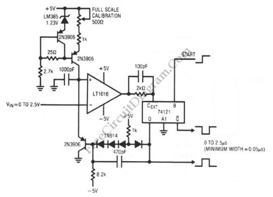
LT1016 – LS74121 Voltage Controlled Pulse Width Generator/ Monostable Multivibrator
Mono-stable multivibrator circuit generates a fixed pulse width when receiving a trigger signal on its input. The pulse width of […]
Read moreFree electronic circuit design and schematic diagram
Mono-stable multivibrator circuit generates a fixed pulse width when receiving a trigger signal on its input. The pulse width of […]
Read moreInterfacing high power load can be done in many ways, such as using voltage divider resistors, transformer, or optocoupler. In […]
Read more
Using an RS232 port, we can generate square wave oscillation when transmitting data, and this can be “misused” as signal […]
Read more
This RS flip-flop is op-amp version of classic flip-flop which uses two inverting amplifier. The non-iverting input is floating, and […]
Read more
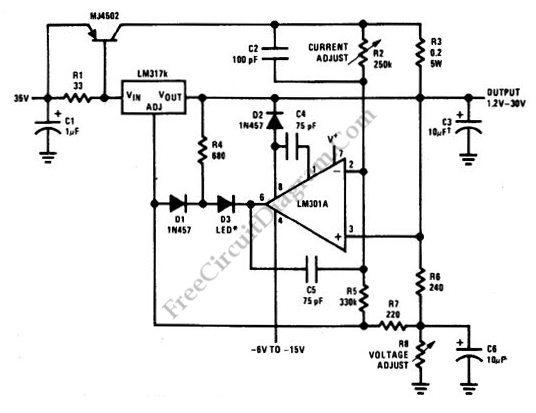
A constant voltage constant current (CVCS) regulator doesn’t mean a system with a constant load, since there will be no […]
Read more
For you those are not familiar with analog circuits, it might seem difficult to find a practical application of analog […]
Read more