You might be familiar with passive crossover network installed inside your speaker box, consist of inductors and capacitors. The problem with passive crossover network is that they dissipate the audio power, so it’s not environmentally friendly, contributing a little disaster of global warming. Moreover, the capacitor and the inductor in the passive crossover network contribute the distortion of the signal since it must drive a low impedance load (the loud speaker). The best way to get high quality audio is to separate the high and low frequencies before feeding the signal to the amplifier. The drawback is that you need two amplifiers, to amplify the low and high audio signal separately. Here is the schematic diagram of the active crossover circuit:
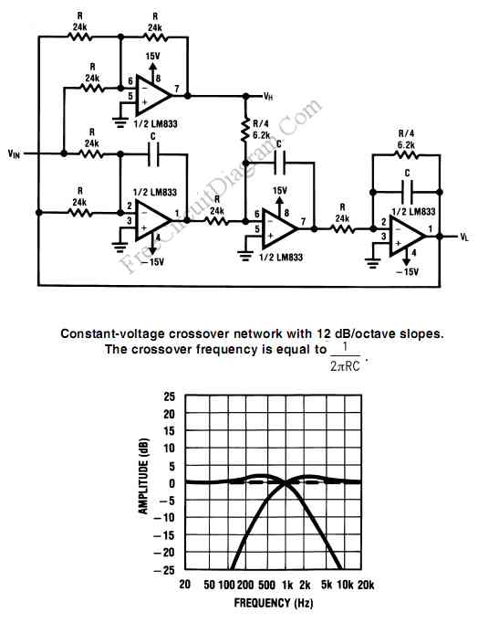
The circuit use a constant voltage method, means that the output of high and low frequency is summed up, and then fed back to be compared with the input to make sure this sum is equal to the input signal. This method ensure that the total response is flat, if we summed back the separated high and low frequency output.
You have to use 1% tolerance for the resistors to give a precise response. According to the formula, the capacitor C should be 6.6nF to give 1kHz crossover frequency, but a 6.8nF can be used because it waidely available, and the crossover frequency will be shifted to about 975Hz. [Circuit's schematic diagram source: National Semiconductor Application Notes]
Possibly Related Articles:
- Crossover Design Using Online Crossover Calculator
Crossover Calculator An online crossover calculator in this link is not only capable of designing 1st order crossover, but 2nd, 3rd, and 4th crossover calculation is also supported. Designing a... - First Order Low-Pass Active Filter: The Circuit Schematic Diagram and The Design Formula
The simple low-pass filter is shown in Figure below. The filter has a 20dB/decade roll-off after its corner frequency fc. Its low-pass frequency gain (f->0) is defined by R3/R1. This... - 1st-order-3-Way Crossover Circuit Design Using Free Online Tool
Designing passive crossover network for your speaker system is easy, just like what shown in our previous crossover design article, but now we can design many types of crossover even... - PC (Audio) Signal Generator Using RS232 Port
Using an RS232 port, we can generate square wave oscillation when transmitting data, and this can be “misused” as signal generator (square wave generator). This is a PC Signal generator... - Phase-Shift Meter for Audio Frequency Signal
Simple phase shift measurement can be done by squaring both the measured and the reference, then compute the difference of the two signals. The accuracy of the circuit shown in... - Active Power Factor Correction Circuit
Active power factor correction stabilize the electrical demand of a device to give the best power factor characteristic of many types of loads. To meet power factor regulation, a low... - LED Audio Level (VU) Indicator and Alarm: The Dot Turns to Bar When The Signal Reach The Maximum Level!
This LED (Light Emitiing Diode) display consist of 10 LEDs to indicate the level of an input signal. If the signal is small, only LED#1 will light, and if the... - Passive Crossover Network Design for Hi-Fi Speaker
Crossover network for speaker can improve the quality of the sound, reducing the distortion level caused by excessive signal beyond the speaker’s frequency response. This articles describes how you can... - Audio Signal Injector/Tracer
This testing instrument provide two alternate fuction: signal injector and signal tracer. This audio signal tracer/injector is very helpful in trouble shooting audio circuits, when you need to test a... - Precision Full-Wave Peak Detector: Detect The Envelope of An Audio Signal
This circuit detect the amplitude of audio signal, suitable for audio level detection that demand for high precision. Amplitude detection or signal envelope detection is usually implemented using a peak... - Split-Phase Data Synchronization and Decoding
A split-phase data signal consists of a series of binary digits that occur at a periodic rate, as shown in waveform A in the timing chart. The weight of each... - Pressure Sensor Signal Conditioning Circuit with Single Op-Amp
This is pressure sensor signal conditioning circuit. It is simple and inexpensive circuit because it has small geometry and simple pressure sensor. It just uses a single Operational Amplifier. This...

| 

