5-Band Graphic Equalizer Circuit Using LA3600 Integrated Circuit Chip
Using a special purpose single IC chip LA3600, we can build a graphic equalizer with low components count. The internal design of the chip uses transistors gyrator circuit, with connections to external capacitors to set the response. This graphic equalizer circuit is suitable for tape-recorders, radio-cassette recorders, car stereos, or home theater sound systems. You need a pair of this circuit to provide a stereo channels. Here is the schematic diagram of the circuit:
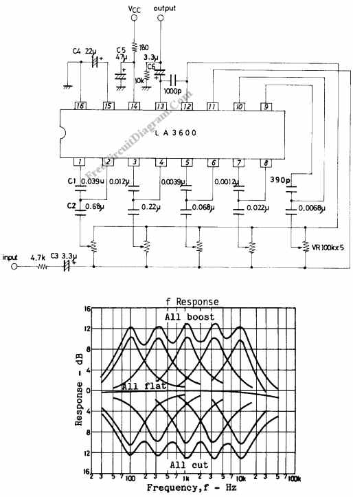
The center frequency for each band fo is determined using the formula:
fo=1/ [2*PI* squarerooot( C1.C2. R1.R2)]
(R1=1.2k, R2=68k on-chip resistor)
Using the component values as shown in the schematic diagram, fo for each of 5 bands is set as follows : fo=108Hz, 343kHz, 1.08kHz, 3.43kHz, 10.8kHz.
Description of external parts
C1, C2 : Capacitors used to fix fo (resonance frequency)
C2 : Input capacitor. Decreasing the capacitor value lowers the frequency response at low frequencies.
C3 : Input capacitor. Decreasing the capacitor value lowers the frequency response at low frequencies.
C4 : Decoupling capacitor. Decreasing the capacitor value makes the effect of power supply stronger, whereby ripple is liable to occur.
C5 : Power capacitor.
C6 : Output capacitor. Decreasing the capacitor value lowers the frequency response at low frequencies.
Maximum supply voltage VCC max 20V must not be exceeded. The operating voltage is in the range of 5 to 15V. Application of power with the pin-to-pin spaces shorted causes breakdown or deterioration of the IC to occur. When mounting the IC on the board or applying power, make sure that the pin-to-pin spaces are not shorted with solder, etc. [Circuit’s schematic diagram source: SANYO Electric’s Application Notes]