Passive Crossover Network Design for Hi-Fi Speaker
Crossover network for speaker can improve the quality of the sound, reducing the distortion level caused by excessive signal beyond the speaker’s frequency response. This articles describes how you can design your own crossover networks for your Hi-Fi speaker set. Both first order and second order passive filter will be explained in this article. First order crossover network will give 6dB roll off curve for the frequency response, and the second order one will give 12dB/octave roll-off.
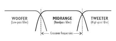
Woover, Mid-range, and Tweeter Speakers
You need a low-pass filter crossover network for woover or sub-woover, a band-pass filter for mid-range speaker, and a high-pass filter for tweeter. Sometimes when you have only two speakers in a set with a woover and a tweeter, then you need only a low-pass and high pass filters. To give a flat response, you need to set the corner frequency of each filter at the same point, so the response of will cross-over (overlapped) in the transition area of each filter band). This point is called crossover frequency point.
The circuit configuration of the circuit is simple, as shown in the figure below. The first order crossover network is the simplest, need only a capacitor for the high pass and and an inductor for the low pass.

Designing A Crossover Network for Two-Way Speakers System
For 2-way speaker system, in case of the first order filter, you just need a capacitor and inductor. Let’s say you have a 8 ohm woover and a 8 ohm tweeter. First you have to select the crossover frequency, say 1 kHz. Then you look-up the table to find the value for the inductor to be installed in series with the woover, and the capacitor to be installed in series with the tweeter. For this case you’ll get 1.2mH for the inductor and 20uF for the capacitor.
If you need a second-order filter for your crossover network, then you need to provide two caps and two inductors. Look at the second table (12dB/octave) 1 kHz, 8 ohm, and you’ll find 1.8 mH and 13uF value for the inductor and capacitor. Provide two 13uF caps and two 1.8mH inductors. One capacitor should be wired in parallel with the woover, and then connected in series with the inductor. For the tweeter, you need to wire the inductor in parallel with the tweeter, then connect the capacitor in series.
Designing A Crossover Network for Three-Way Speakers System
For three-way speaker system, you need to define the first crossover point f1 for transition between low frequency and mid frequency, and the second crossover point f2 for the transition between mid frequency and the high frequency. Let say you have an 8 ohm woover, 8 ohm mid-range speaker, and an 8 ohm tweeter. Let’s define the crossover frequency f1=500Hz and f2=10KHz.
If you want a first order filter (6dB/octave roll-off), look at the table for 200Hz, 8 ohm. You’ll find a 9mH value for the inductor. Connect this inductor to your woover in series. For the mid-range speaker, you need a capacitor and an inductor to be wired in series. Look the value of capacitor using the f1 (200Hz), and look the value for the inductor using f2 (10 kHz). You’ll need a 70uF capacitor and a 0.18mH inductor to be wired in series with the mid-range speaker. For the tweeter, you have to choose the capacitor value for f2 (10 kHz) at 8 ohm, a 1.4 uF capacitor will be needed.
For the second order filter (12dB/octave roll-off), f1 (200 Hz) should be used for selecting the capacitor-inductor pair for the woover. For the tweeter, capacitor-inductor pair should be selected based on f2 (10 kHz). For the mid-range, there a two pairs of caps-inductor, i.e. L1-C1 and L2-C2 (see the last circuit wiring schematic in the figure). The first pair (Li-C1) should be chosen based on f1 (200 Hz) and the second pair (L2-C2) should be based on f2 (10 kHz).
Choosing The Right Components
For inductor, the best component is air-core inductors since it doesn’t suffer much distortion from core’s hysteresis. The iron-core is not acceptable because it introduce a lot of distortion. For bigger value, a ferrite-core is acceptable. Stick with air-core coils for small value inductors. The lower the resistance the better the performance since it dissipate less power. Dissipate less power means less temperature changes that minimize the resistance variation that cause a non-linear distortion.
For capacitors, a metalized polypropylene types will be the best, but for larger value, a polar electrolytic caps is acceptable. Use capacitors with low ESR (equivalent series resistance). The series resistance in a capacitor cause a similar effect with the inductor’s resistance as we have explained before. If the capacitor’s value is somewhere in between the available values, then use it parallel to get an arbitrary value, for example, for 13uF, you can use a 10uF and 3.3uF caps connected in parallel. This gives us a 13.3 uF value, close to what we need. This appproximation is acceptable because the component itself is actually has no precise value, but rather has a tolerannce about 5% around its nominal value. Moreover, the speaker impedance that we use as the reference for selecting the C-L value is variable, depending on the frequency. Using the same way, arbitrary inductor value can also be implemented using combination of two inductors, but unlike the cpacitor, the inductors should be connected in series.