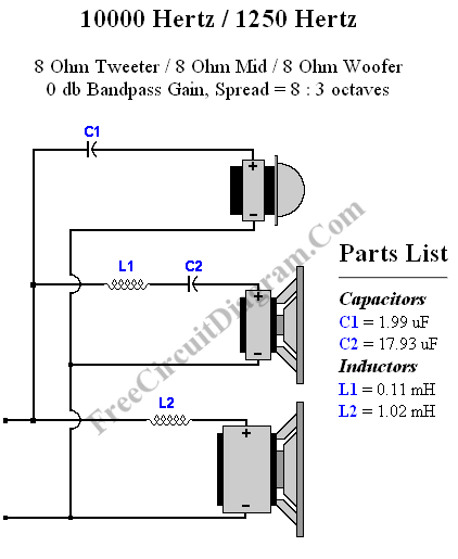
Designing passive crossover network for your speaker system is easy, just like what shown in our previous crossover design article, but now we can design many types of crossover even easier using online crossover design tool. The crossover schematic diagram here is an example with a case of 10 kHz high corner frequency, 1250 Hz low corner frequency, 8 ohm woover, 8 ohm mid, and 8 ohm tweeter.

For different design parameters of this 1st order crossover network circuit (6dB/octave roll-off frequency response), you can go to the online crossover design calculator here. [Source: diyaudioandvideo.com]
Possibly Related Articles:
- Crossover Design Using Online Crossover Calculator
Crossover Calculator An online crossover calculator in this link is not only capable of designing 1st order crossover, but 2nd, 3rd, and 4th crossover calculation is also supported. Designing a... - First Order Low-Pass Active Filter: The Circuit Schematic Diagram and The Design Formula
The simple low-pass filter is shown in Figure below. The filter has a 20dB/decade roll-off after its corner frequency fc. Its low-pass frequency gain (f->0) is defined by R3/R1. This... - Passive Crossover Network Design for Hi-Fi Speaker
Crossover network for speaker can improve the quality of the sound, reducing the distortion level caused by excessive signal beyond the speaker’s frequency response. This articles describes how you can... - Butterworth Second Order High-Pass Filter: The Circuit and The Formula
For high pass filter, this circuit is similar to low-pass filter circuit, but the position for resistors and capacitor are interchanged. Here is the circuit’s schematic and formula: Similar with... - Active Crossover Circuit: Split The Audio Signal Before Amplification
You might be familiar with passive crossover network installed inside your speaker box, consist of inductors and capacitors. The problem with passive crossover network is that they dissipate the audio... - Second Order Butterworth Low-Pass Filter
A second order filters can be constructed using LC (inductor-capacitor) passive circuits, and they have been implemented for radio frequency for cheap and simplicity. For audio frequency range, unfortunately the... - Dynamic Compressor, Self Powered Circuit Design
This dynamic compressor will give about 20dB compression, at very wide input signal range 100 mV to 10 V. Another advantage of this circuit is that this circuit doesn’t need... - Free Electricity from Your Telephone Line – Video Tutorial
This is a video about free hidden electricity. This video discover the secret source of electricity that the power company and phone company hide. To discover this secret source, we... - Differential Low-Pass Filter and The Design Formula
Multiple Feedback (MFB) is the best filter topology to use for differential low pass filters. Here’s the circuit diagram: To design this filter, a corner frequency is chosen based on... - Notch Filter: The Circuit’s Diagram and The Design Formula
Notch filter is known as band-cut filter or band-reject filter. The fuction of this filter is to remove some frequency portion of a signal. The schematic diagram of this filter... - Single Chip Stereo FM Transmitter Circuit: A Very Compact Design
ROHM (www.rohm.com) is originally a resistor producer company, but finally expand their business and produce monolithic IC, and this one used in our circuit is the example. The internal structure... - Current Sense Circuit, A Classic Design Using Positive Rail Sensing
A LT1637 is advertised as 1.1MHz, 0.4V/us Over-The-Top Micropower, Rail-To-Rail Input and Output Op Amp. This features are suitable for current sensing application since input voltages are right at the...
| 

