Dynamic Compressor, Self Powered Circuit Design
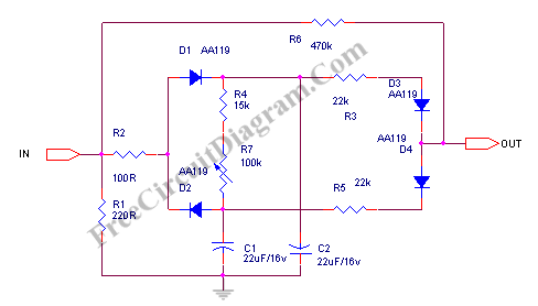
This dynamic compressor will give about 20dB compression, at very wide input signal range 100 mV to 10 V. Another advantage of this circuit is that this circuit doesn’t need any power supply, we call it self powered, or more accurately, signal-powered compressor. Here is the schematic diagram of the circuit:
A part of the signal is rectified by D1 and D2 and is used to charge C1 and C2 Capacitors. This current control the attenuator diodes D3 and D4, together with R3, R5, and R6. The attenuator diodes work at the nonlinear region of the forward current curve. At low level, the input signal is not attenuated since the rectified voltage is under voltage bias of D3 and D4, since that D3 and D4 become non-conductive. If the level of input signal increase, at some point, the D3 and D4 begin to conduct and attenuate the signal.
The attack time of this compressor circuit is fixed and is determined by time constant of C1, C2, R2, and the output impedance of the input source that feed this compressor input. The decay time can be slightly adjusted by R7 variable resistor. You can see that the signal path of this compressor circuit use a 470k resistor as the attenuator, means that you should only connect the output of this circuit to a high impedance stage.
This circuit works best with germanium diodes, since it has lower forward bias voltage and also smoother curve than silicon diodes. Using silicon diodes will works but the performance would be degraded. [Source: Elektor]