Analog Compensation Circuit for PT100 RTD Temperature Sensor

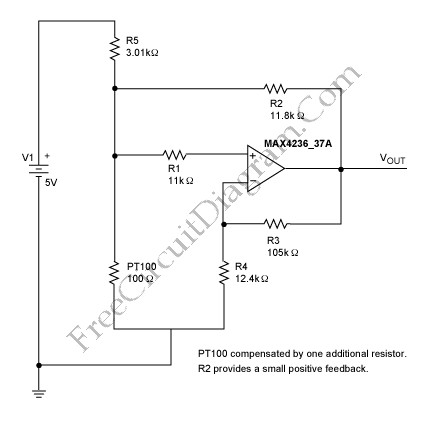
There are some digital and analog that can be used for compensating a PT100 RTD nonlinearity. We can implemented the digital linearization by implementing the previous generic equation or by a lookup table. By implementing the previous generic equation we can calculate temperature values directly, based on the actual measured RTD resistance. A lookup table allows an application to convert a measured PT100 resistance to the corresponding linearized temperature, it located in µP memory . Those methods have some disadvantages, if we use the previous generic equation method, some CPU time must be sacrificed to do the math. If we use the lookup table then we must must first identify the two closest resistance values and then interpolate between them. A lookup table necessarily contains a limited number of resistance/temperature values. The main drawback of the digital linearization is the need of a microprocessor (µP). To avoid employing a microprocessor, we can use the analog approach to perform accurate linearity compensation. Here is the circuit :

This circuit linearizes the raw PT100 output. Without any linearization, the output of the sensor deviate from its linear model about -1.5 to 0.5 Celsius degree within -50 to 125 Celsius degree operating range. Using analytic calculation of this circuit model, it can be shown that the deviation from its linear model (the linearity error) can be reduced to maximum 0.05 Celsius degree within that range. [Source: Maxim-ic.com]