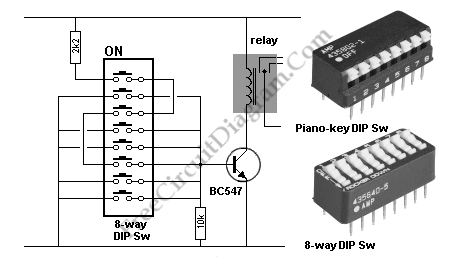
This is Simple Code Lock circuit. This circuit will turn on a relay when the 8-way DIP switches receives the correct code.  Here is the schematic diagram of the  circuit:

Simple Code Lock circuit schematic

There are two different types of DIP, they are piano-key DIP sw and 8-way DIP sw. This circuit will not draw the current if the switch is kept off. This circuit can give 256 different combination because the combination is in binary. So it would be very difficult for a burglar to keep up with the settings of the switches.  [Source: talkingelectronics.com]


Possibly Related Articles:

  • PLL Lock Detection
    In some PLL application, sometimes we need to provide lock indication when the PLL is in locked state. The simplest one is binary indication, 0 or 1 to correspond with...
  • Simple Lie Detector
    To know someone is lying  or not we can use lie detector. This is a simple lie detector that can be made in minutes. It works to detect the someone...
  • Simple pH Meter
    pH Meter Circuit pH meter measures the voltage (the EMF, electromotive force) generated by the pH electrodes (the sensor) to show the hydrogen concentration in pH scale. Basically, a pH...
  • Simple Digital Theremin
    Theremin circuit shown in this schematic diagram uses digital component, so we can call it a digital Theremin. This circuit employs  logic inverter 74C04 or CD4069 hex inverter and CD4046...
  • Simple SWR Meter Bridge
    Standing wave ratio(SWR) is a ratio of amplitude of partial standing wave at maximum to amplitude at minimum. Using a Simple Swr Bridge circuit, a SWR can be measured. This...
  • Simple LDR Light Alarm
    This is a light alarm circuit. This circuit uses Light dependent resistor (LDR). When there is no light fall on the LDR, the transistor driving the speaker is not turned...
  • Simple Signal Injector
    This is a signal injector circuit.  Signal injector is important tool for troubleshooting your electronic circuits. As an example, this circuit can be used to test amplifier circuit.  Here is...
  • Simple Wideband SWR Meter
    This is a circuit of Wideband SWR Meter. This circuit is used as a test instrument. To use this circuit, connect the meter, take the necessary readings, then disconnect. The...
  • Simple Audio Amplifier
    This is an audio amplifier circuit which has power of 18W. It is very simple but it has a high quality. This circuit does not require pre amplifier. It can...
  • Simple Transistor Tester Using 555 IC
    Testing whether a transistor is shorted or open usually done by ohm meter. You test if the base to emitter  or collector permit a current flow in one direction. Here...
  • Simple Touch Switch Using 555 IC
    This 555 circuit will activate a buzzer and turn on a LED lamp when you touch the probe. Here is the circuit’s schematic diagram: lf you touch the plates, the...
  • Simple Humidity Sensor
    You can use a humidity sensor to give an alert of boat leakage, or when your books start being flooded by heavy rain attack on your broken roof, or anything...