Digitally Controlled Dual Polarity Amplifier

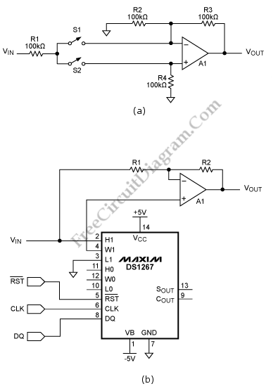
This schematic diagram below shows a Digitally Controlled Dual Polarity Amplifier circuit. The circuit (a) can give a means of amplifying a signal either in non inverting and inverting mode. When S2 is off and S1 is on, the noninverting input of the op amp is fed by the signal. The circuit behaves as a regular inverting amplifier, When switch S2 is on and S1 is off. A digital signal can be used to control the circuit if S1 and S2 are monolithic analog switches. Here is the schematic diagram of the circuit:

A potentiometer can be used to replace the switches as shown in circuit (b). When the wiper is at the high end of the pot, the noninverting mode is chosen and the inverting mode will be selected when it’s at the other end. Circuit (b) uses DS1267 linear digital potentiometer. This circuit not only gives digital control of the polarity but also the amplifier gain. To accomplish the signal processing task, an “extra” pot in a circuit to be used because the digital potentiometers come in dual configurations. The DS1267 has the 3-wire interface, they are active-low CLK, RST and DQ. A wiper value of 11111111 will set the wiper to the high end of the pot, so the circuit is in a noninverting configuration with gain = +1. an inverting configuration with gain = -1 is chosen when wiper value is 00000000 that set the wiper to the low end of the pot. [Circuit’s schematic diagram source: maxim-ic.com]