555 IC Linear Ramp (Sawtooth) Generator/Oscillator

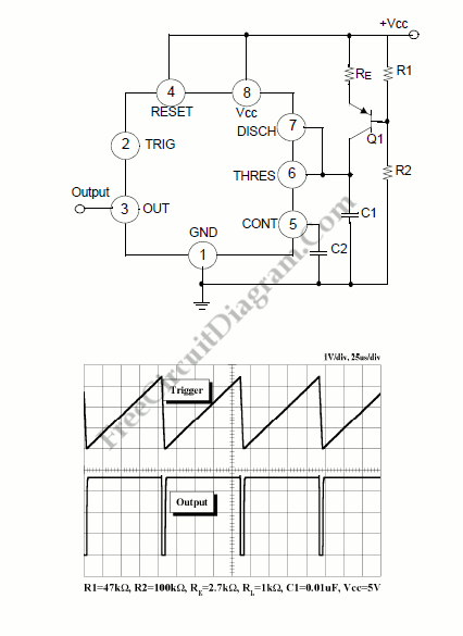
The Vc1 increases linearly when the pull-up resistor RA in the monostable circuit is replaced with constant current source, generating a linear ramp. The linear ramp generating circuit and the generated linear ramp waveforms illustration is shown in figures below.
 Current source is created by PNP transistor Q1 and resistor R1, R2, and Re.
Ic= (Vcc-Ve)/Re
Ve= Vbe + (R2/(R1+R2))Vcc
For example, if Vcc=15V, RE=20k, R1=5kW, R2=10k, and VBE=0.7V, VE=0.7V+10V=10.7V, Ic=(15-10.7)/20k=0.215mA
The current flowing through capacitor C1 becomes a constant current generated by PNP transistor and resistor when the trigger starts in a timer configured as shown in figure below.
Hence, the Vc is linear function. The gradient S of the linear ramp function is defined as:
S= (Vp-p)/T
The Vp-p is the peak to peak voltage. The Vc comes out as follows is the electric charge amount accumulated in the capacitor is divided by the capacitance.
V= Q/C
The above equation divided on both sides by T gives us
V/T= (Q/T)/C
and may be simplified into the following equation.
S=I/C
In other words, we can obtained the gradient of the linear ramp function appearing across the capacitor by using the constant current flowing through the capacitor. The gradient of the ramp function at both ends of the capacitor is S = 0.215m/0.022? = 9.77V/ms if the constant current flow through the capacitor is 0.215mA and the capacitance is 0.02uF. [Circuit’s schematic diagram source: Philips Semiconductors Application Notes]