74HC11 Infra-Red Remote Control Tester

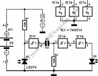
This is Infra-Red Remote Control Tester circuit. This circuit is used to test go/no-go of any remote control transmitting infra-red (IR) light. The supply of this circuit is 3V battery. This circuit has some advantages, such as fits in a compact enclosure, built from inexpensive parts and a handful of commonly available. As a quasi-analogue amplifier, this circuit uses Schmitt trigger gate IC1f with the sensor element.
Here is the schematic diagram of the circuit:
The sensor element is an infra-red emitting diode (IRED) type LD274. All IR remote controls transmit pulse bursts, so an R-C network, C1-R2, is used at the output of the gate. Beside that, An R-C network is also used to prevent the output LED, D2, lighting constantly when another continuous source of IR light or day-light is detected. [Circuit’s schematic diagram source: extremecircuits.net]