Enabling 3 Phase Motor to Operates with Single Phase Supply

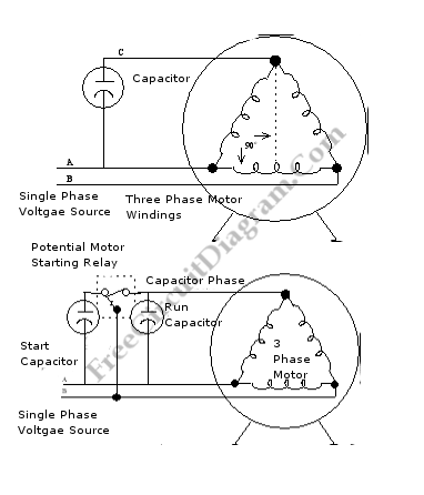
Capacitor have been use for decades to operate 3-phase motors on single-phase power. Two single-phase wires are connected to two of the inputs on a 3 phase motor on this method. Then, the capacitors is connected to one of the single -phase inputs and the third leg of the motor. Here is the schematic diagram of the circuit:

The voltage is allowed to be displaced in time from its parent voltage by phase shift through the capacitor. Voltage distinct from the 2 single-phase lines is the result. The motor will operate if the capacitors value-it’s ability to process electrical current- is sufficient.
6 times as much current to start as it does to run is required by the motor so a static-capacitor phase converter must have some means of switching a large group of capacitors in and out during motor starting. Below is a typical unit uses a potential-type motor starting relay (pirated from a single-phase motor) to regulate the larger start capacitor, while a smaller (in value) capacitor provides continuous power to run the motor. The potential relay removes the start capacitor from the circuit as the motor speed increase, and the motor operates. [Circuit’s schematic diagram source: gwm4-3phase.com]