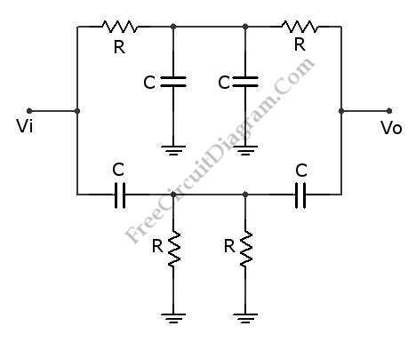
This is a Twin-T Notch Filter circuit. This circuit is a filter that can remove a certain frequency band. This is a passive filter that uses two filters in parallel, high-pass and low-pass. The high-pass filter is lower one and the low-pass filter is the upper one. This filter has a problem with the input resistance. When this filter is used on high frequencies, the input resistance is low about R/4. Beside that, this filter properties depend on the load and the source since this is a passive filter. It can be solved by buffering the filter. Here is the circuit:

The minimum gain frequency of this circuit is determined by following equation:
fo = 1 / 2piRC
If the wanted fo is 1591 Hz, the R should be 10K and the C should be 0.01uF. When R=2.7 and C=1uF are used, the filter will block frequencies of 60Hz. By adjusting the frequency until the gain is 0.707 at the low and high points will give the frequencies fL and fH for the -3 dB points. So we can estimate the bandwidth of the filter. The Q of this circuit is determined by following equation: fo/(fH – fL)
And the center frequency divided by the bandwidth.
Possibly Related Articles:
- Variable Q Twin-T Notch Filter
This is a Variable Q Twin-T Notch Filter circuit. This circuit is used when low Q is needed. The Lower Q gives some advantages in rejecting the signal where the... - Bootstrapped Twin-T Notch Filter Produces High Q
This is a Bootstrapped Twin-T Notch Filter circuit. This circuit can generate high Q by combining the twin “T” with LM102 voltage follower. The generated Q is greater than 50.... - Transistor Hum Notch Filter
The function of this circuit is similar with the hum filter in our previous circuit, but it use transistors instead of op-amps. It uses BC109 transistors, but any low noise... - Notch Filter: The Circuit’s Diagram and The Design Formula
Notch filter is known as band-cut filter or band-reject filter. The fuction of this filter is to remove some frequency portion of a signal. The schematic diagram of this filter... - Voltage-Controlled Low-Pass Filter with LM13600 OTA
Below is a circuit that demonstrates one use of an OTA using an LM13600. Take a note that the strange symbol stand for OTA. In this circuit, negative feedback is... - Differential Low-Pass Filter and The Design Formula
Multiple Feedback (MFB) is the best filter topology to use for differential low pass filters. Here’s the circuit diagram: To design this filter, a corner frequency is chosen based on... - Low Pass Filter with Enhanced Step Response
Effect on the system’s time-domain response is a common problem when designing lowpass filters. The system may fail to recognize significant changes in time because pushing the cuttoff frequency lower... - Sallen and Key Lowpass Filter
This a Sallen and Key Lowpass Filter circuit. This circuit is a second-order active filter. This circuit can be changed to highpass filter by interchanging capacitors and resistors. This circuit... - Second Order Butterworth Low-Pass Filter
A second order filters can be constructed using LC (inductor-capacitor) passive circuits, and they have been implemented for radio frequency for cheap and simplicity. For audio frequency range, unfortunately the... - Hum Filter, An Ultimate Weapon To Remove AC Line Noise
You might think that hum noise is produced by electronic device with improper design, yes you’re right. And you might choose to solve the trouble maker, the source. You begin... - Infrasonic and Ultrasonic Filter for High Fidelity (Hi-Fi) Audio System
In high fidelity (hi-fi) audio system, the harmonic distortion level is kept as low as possible. To make sure that the amplifier handle the sigal perfectly, the response of many... - Butterworth Second Order High-Pass Filter: The Circuit and The Formula
For high pass filter, this circuit is similar to low-pass filter circuit, but the position for resistors and capacitor are interchanged. Here is the circuit’s schematic and formula: Similar with...
| 

