TC9400 Frequency-to-Voltage Converter

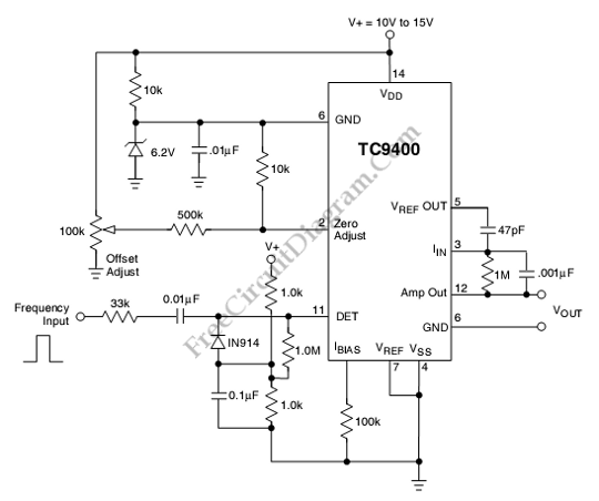
This is a TC9400 Frequency-to-Voltage Converter circuit. Beside used as voltage to frequency converter, the TC9400 can also used as Frequency-to-Voltage Converter. The TC9400 will convert the input frequency waveform to output voltage linearly. This circuit has a threshold detector’s input that is used to detect each zero. The zero will cause a precise amount of charge(q=Cref Vref) to be dispensed into the summing junction of Op-amp. The op-amp output produces the voltage pulses from the charge flows across the feedback resistor. The output voltage is linearly proportional to the input frequency because the output is DC voltage. The capacitor(cin) across the Rint averages the output voltage to DC voltage. Here is the schematic diagram of the circuit:

The output voltage is determined by following equation:
Vout=(Vref*Cref*Rint)Fin
The time response of this circuit is equal to (RintCint). The output voltage has ripple which is inversely proportional to the input frequency and Cint. To lower the ripple, the Cint can be increased. For low frequencies the perfect value of Cint is 1µF to 100µF. The Vref is defined as the voltage difference between pin 2 and pin 7 because the TC9400 is used in single supply mode. [Circuit’s schematic diagram source: Microchip Datasheet]