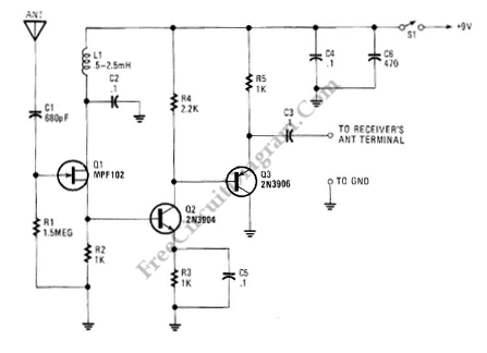
This is an active antenna circuit with gain. This circuit is used to bost the signal. This circuit is made from a few transistors and other components. This circuit can provide RF gain of about12 to 18 dB. This circuit uses Q2 as a voltage amplifier. the RF signal direct-coupled from Q1’s Source terminal to the base of Q2. The Q3 is configured as an emitter-fallower amplifier which match and isolate the gam stage from the receiver’s RF-inputcircuitry. Here is the schematic diagram of the circuit:
The bias of Q2 is set to 2V by the value of R2. The value of R2 can be increased to 1.5KΩ if the voltage is less than 2V. The power source noise never reach the FET because of inductor L1. Set value of C1 to 0.002 μF if need to go to below 100 kHz. The antenna is Short pull-up type.
Possibly Related Articles:
- UHF Antenna Booster
UHF antenna booster can be used for better reception, especially when you’re far from TV station / relay transmitter. This UHF antenna booster works in 400-850 MHz range. Here is... - AM/FM Antenna Booster
This antenna booster circuit can be used to amplify the weak signal received by the antenna. Antenna for AM/FM is usually not tuned for the optimal dimension of 1/4 wavelength,... - VHF-UHF Antenna Amplifier (Booster) 40-500MHz
This amplifier has VHF (very high frequency) and UHF (ultra high frequency) response, you can use it for receiver booster for example. Here is the schematic diagram of the circuit:... - Voltage Controlled Variable Gain Amplifier
This is a circuit of voltage controlled variable gain amplifier. This circuit uses 2N4391 that will provide a low Rds(on) less than 30 Ohm. This circuit also uses a tee... - Voltage Controlled Variable Gain Video Amplifier
This is a video amplifier circuit featured with controllable variable gain. The control is done by adjusting the voltage of grid inputs of two FETs, which are configured as programmable... - Discrete Active Virtual Ground
You might find op-amp based active virtual ground, but here a schematic diagram shows that you can build such circuit using discrete components. This circuit uses most any complementary pair... - Active Power Factor Correction Circuit
Active power factor correction stabilize the electrical demand of a device to give the best power factor characteristic of many types of loads. To meet power factor regulation, a low... - How to Pre-Tune a Ham Radio Antenna – Video Tutorial
This is video about how to pretune a ham radio antenna. This video shows how to tune a ham radio. In this video, the antenna is tuned to make sure... - Active Crossover Circuit: Split The Audio Signal Before Amplification
You might be familiar with passive crossover network installed inside your speaker box, consist of inductors and capacitors. The problem with passive crossover network is that they dissipate the audio... - First Order Low-Pass Active Filter: The Circuit Schematic Diagram and The Design Formula
The simple low-pass filter is shown in Figure below. The filter has a 20dB/decade roll-off after its corner frequency fc. Its low-pass frequency gain (f->0) is defined by R3/R1. This... - Stereo VU Booster Circuit using Transistors
This is a Stereo VU Booster circuit. In this circuit, shown in the schematic diagram, transistor FCS9014 is used. Actually you can use almost any type of small signal NPN... - Discrete Bass Booster Circuit
This bass booster circuit can be used filter the input signal as part of internal circuit of an active subwoofer circuit. This circuit is not only boost the bass (low)...

| 

