Voltage and Current Limited Audible Continuity Tester

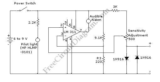
Using this continuity tester circuit, a failure of PCB tracks be examined without looking directly at the tracks routing, which is can be very frustrating. The indication of this circuit is done by an audible alarm (a buzzer). This circuit can be used to indicate continuity below any resistance value up to 35 ohms by adjusting the circuit. To make sure this circuit doesn’t damage any installed parts on the board, the voltage and current of this circuit is limited. Here is the schematic diagram of the circuit:

The mechanism of this continuity tester is very simple. The core of the circuit is an LM311 comparator, which compares the voltage at the inverting and the non inverting inputs. The buzzer (audible alarm) will be activated if the output of the comparator is grounded/low, and this condition is produced if the non-inverting input is lower than the inverting input, when the voltage at the probe is shorted to ground by a good continuity at the tested PCB/conductor track.
The maximum current through the probe is limited to 3 mA by a 3k resistor, and the maximum voltage is limited to 0.6V by the 1N916 diodes. With the current and voltage limiter feature, this circuit can be safely used for PCB even with complementary metal oxide/semiconductor integrated circuits is installed on. If this circuit is set to 30 ohms, the audible tone will sound when the resistance between probes is 30ohms or less and remain silent when the resistance is greater than 30ohms. The pilot light can be replaced with a standard LED, as it is only used as power indication.