22W Amplifier for 12V Power Supply Systems
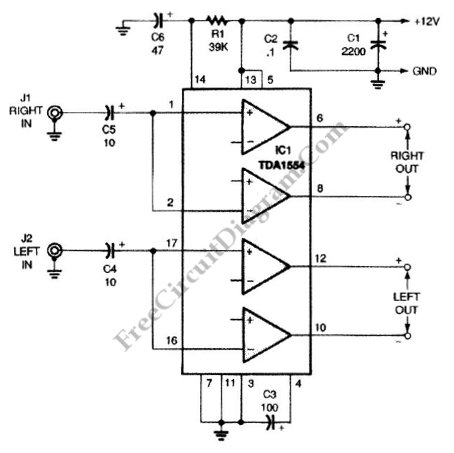
This is a 22-W Amplifier circuit that is designed for or 12-V DC power supply Systems. There are many application for this circuit, such as in car audio application. In car electrical power supply system, the 12V power supply will be provided by the host vehicle’s battery. The capacitor C3 is used to give ripple rejection, since noisy power supply voltage is common in automotive electrical system. The power supply noise signal on car power supply is decoupled by the capacitors C2 and C1. Smaller capacitor C2 is needed to decouple the high frequency noise, since the larger cap (C1) usually has high equivalent series inductance that prevent the high frequency noise (such as glitch or spike) to be bypassed. The capacitors C5 couple the incoming audio signal to IC1 while decoupling static DC offset. For better bass response, this circuit prevent rolling off of the low audio frequencies by choosing a relatively large capacitance for small signal, 10μF capacitors. Here is the schematic diagram of the circuit:
This circuit prevent power supply pop noise by muting the amplifier at the power-up. The mute input (pin 14) is fed by capacitor C6 and Resistor R1, giving delay on power-up which prevent turn-on pop. This R/C time constant gives about 1.4s delay to keep the output muted, enough to make sure the amplifier reach the stable state after powered up. About how this muting works, the amplifier will be ON if pin 14 has at least 8.5 V. The chip will remain in muted condition if the voltage at this pin is below 3.3V. This input pin need very low current consumption, only about 100 pA for standby (muted) and around 40 pA when active. The R1 values must be no larger than 100,000 Ω. The R1/C6 constant should be on the second order. If time constant is too short, the turn-on pop will still be heard, but too long time constant will give unpleasant delay.